10
2
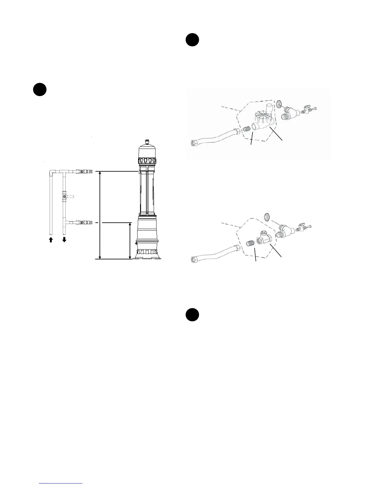
The two inlet/outlet tting assemblies are shipped
pre-assembled, with the mini ball valves and plugs already
installed. Ensure that the plumber tape at both threaded ends
are in good condition. Assemble the inlet and outlet tting
assemblies as shown.
Inlet Fitting Assembly
Mini Ball Valve
with Plug
Inlet/Outlet
Fitting
Stainless Steel
Flex Hose
For models
equipped with
Surface Water
Option Kit only
Inlet Solenoid
Valve
3/4” MNPT
Nipple
Inlet port of
System
Figure 8
The directional arrow on the inlet solenoid valve must point in
the direction of the water ow.
Outlet Fitting Assembly
Mini Ball Valve
with Plug
Inlet/Outlet
Fitting
Stainless Steel
Flex Hose
For models
equipped with
Surface Water
Option Kit only
3/4” MNPT
Nipple
Check
Valve
of System
Figure 9
The directional arrow on the check valve must point in the
direction of the water ow.
3
Install the drain solenoid valve (normally closed) to the
1/2" nipple to the drain port of the system. The directional on
the drain solenoid valve must point in the direction of the
water ow (i.e. away from the system). Install the nylon elbow
to the ow exit port of the drain solenoid valve.
Pipe Assembly and Installation
Ensure that all threaded connections are tted with NSF
approved plumber tape or pipe dope (for potable water) to
prevent leakage.
For systems being installed on surface water applications, the
surface water kit must be installed.
1
Turn o water supply where the water enters the home.
Plumb the inlet pipe at approximately 48" (122 cm) and the
outlet pipe at approximately 20" (50 cm) o the ground. Install
water shut-o valves on the new plumbing. The terminal ends
of the new plumbing must be a 3/4" MNPT adapter in order to
use the supplied stainless steel ex hoses.
Outlet 20”
(51cm)
Bypass
Valve
(optional)
Inlet Valve
Outlet
Valve
Inlet 48”
(122cm)
Figure 7
NOTE: The water bypass in the gure only bypasses the
system. This conguration may be required according to the
local plumbing code in your area.
 Loading...