11
4
Applicable to Systems in Non-Surface Water
Applications Only:
Connect the inlet and outlet tting assemblies to the 3/4"
MNPT ends of the new plumbing with the supplied stainless
steel ex hoses.
Applicable to Systems Equipped with the Surface Water
Option Kit Only:
Select a location on an adjacent wall, with adequate support
(e.g. wall studs), between the stainless steel ex hose of the
inlet tting assembly and the inlet line of the new plumbing.
Follow the instructions described under the Surface Water
Option Kit Installation section in this manual to install the
external prelter. Connect the stainless steel ex hose on the
inlet tting assembly to the external prelter. Once nished,
connect the external prelter to the 3/4" MNPT end of the new
inlet plumbing.
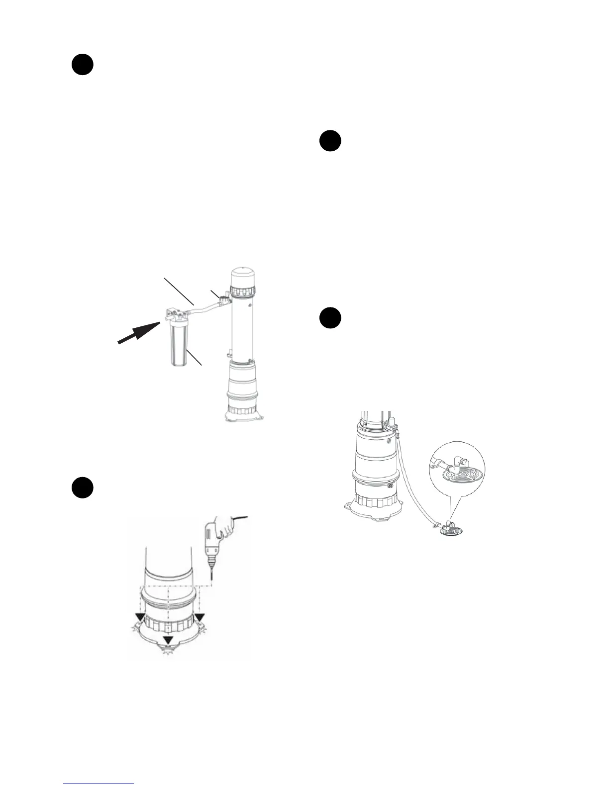
External
Prefilter
Inlet
Solenoid
Valve
To ¾” MNPT end of
the new Inlet
plumbing
Stainless Steel
Flex Hose
Figure 10
Connect the stainless steel ex hose of the outlet tting
assembly to the 3/4" MNPT end of the new outlet plumbing.
5
Securing to the oor. Drill a 3/8" hole through the feet of
the system base.
Figure 11
To level the system, insert the supplied shims beneath the feet
of the system base. Check with a level. Once leveled, fasten
the system to the oor with the supplied 1/4" x 2-1/2" anchors
(for concrete oor) or use screws (not supplied) for wood oors.
NOTE: If the system is being installed on a heated oor, use a
2' x 2' patio stone, that is securely anchored to the oor, for a
base. Do not drill the oor.
6
Apply plumber tape to the 1/4" threads on the air relief
valve. Using a hex key, remove the plug that is located at
the top of the system cap. Thread the air relief valve into the
opening. Do not use tools to tighten the air relief valve to the
system cap as it may cause damage. Loosen the black cap of
the air relief valve 1-1/2 turns to allow for proper venting. Do
not use pliers to take out plugs.
Inlet Fitting Assembly:
Follow the instructions in the Pipe Assembly and Installation
section to assemble the inlet tting assembly. If the surface
water option kit is installed, rotate the inlet solenoid valve
right-side-up.
Final Plumbing Assembly
1
Fasten a drain hose to the nylon elbow of the drain
solenoid valve. Run the drain hose to a oor drain, sink or
dedicated drain that can accommodate the pressure and ow
created during a ush/drain cycle. The drain hose must be free
of kinks and leaks. Fasten the hose to the oor or wall and
direct the hose into the drain with an elbow or clamp. Ensure
that the drain hose can withstand the pressure of the home’s
water supply.
Drain hose must be
anchored down to the
floor or wall and
directed down into the
drain
The local plumbing
code may require
an air gap to be
installed at the
drain line.
Figure 12
All systems will have a pressurized ush sequence during the
cleaning cycle. Depending on the controller program selected,
the system may also have a draining sequence. Refer to the
Setting the Controller section for detailed information on
ushing and draining cycles. The following are recommended
drain line discharge set-ups for the systems.
NOTE: Drain conguration must comply with the local
plumbing codes.
For Systems That Have Only Flushing Sequences (Program
 Loading...