15
Controller Functions
A. Manual Flush
NOTE: For use when the instructions in this manual or the
Owner's Manual call for a manual ush.
To manually ush the system, press NEXT once. “MANUAL”
ashes on the screen. Press MANUAL FLUSH to open the drain
solenoid valve. If the MANUAL FLUSH button is held down for
5 seconds, the drain solenoid valve will remain open for 5
minutes. To interrupt ushing, press MANUAL FLUSH again.
The drain solenoid valve will be closed automatically after 5
minutes if not interrupted.
B. Light and Alarm Function:
The green light on the controller indicates that the system is in
operation. The green light will be ON for 10 months from the
rst commissioning of the system.
WARNING: The green light is NOT an
indication of the integrity of the membrane inside the
system.
At the start of the system’s 11th month of operation, the
yellow service indicator light will come on. This is an indication
that the system’s annual maintenance is required.
After 11½ months of operation, the yellow service indicator
light will begin to ash and an audible alarm will start to beep.
To temporarily silence the alarm, depress and hold the UP and
DOWN arrows together for three seconds. The alarm will come
back on in seven days after this command is executed.
To permanently turn the alarm o, depress and hold the UP
and DOWN arrows together and press ENTER. “A oF” (alarm
o) will appear on the screen. To turn the alarm on again,
repeat the above step. “A on” (alarm on) will appear on the
screen.
To reset the controller, press NEXT and ENTER together and
hold for three seconds. The yellow light will go o and the
green light will come on again.
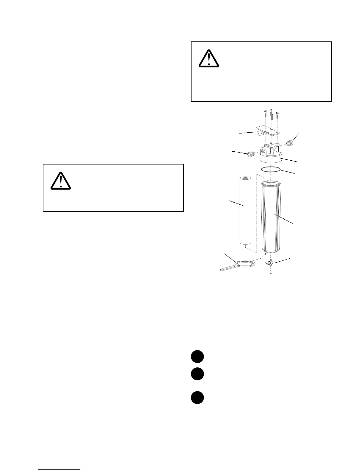
Surface Water Option Kit Installation
WARNING: For all surface water
installations, the Homespring Certied Technician must
inform the homeowner and home occupants that the
entire water supply and distribution system of the
dwelling must be disinfected prior to use.
1” x ¾”
MNPT
Adapter
Housing
Wrench
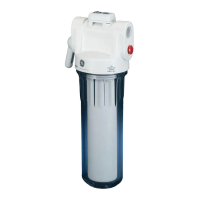
External
Prefilter
housing
External
Prefilter
cartridge
Wall
Bracket
O-ring
External
Prefilter
head
1” x ¾”
MNPT
Adapter
Mini Ball
Valve
with Plug
Figure 19
The surface water kit is purchased separately from the system.
Install this kit in surface water applications.
For convenience of servicing, install the external prelter
between the inlet valve and the inlet tting assembly.
The inlet solenoid valve (normally open) must be installed
as part of the water inlet line and the check valve must be
installed as part of the water outlet line. Refer to Step 2 in the
Pipe Assembly and Installation section.
1
Mount the wall bracket to the wall.
2
Attach the external prelter head to the wall bracket
using the four supplied lag bolts.
3
Remove the plastic wrap on the external prelter
cartridge and insert the cartridge into the external prelter
housing.
 Loading...