24
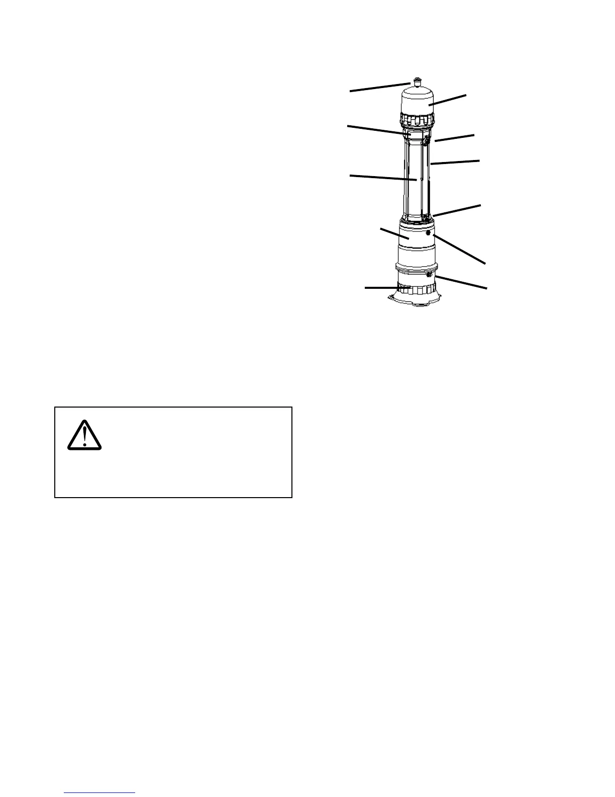
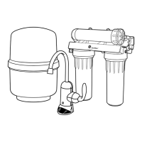
Part Identication
System Cap
Backpulse Tank
System Base
Air Bladder
Valve
Outlet port
Drain port
Inlet port
Air Relief Valve
Membrane
Module
Internal
Prelter
System Casing
Figure 34
Horizontal Mounting
If this installation requires the system to be installed
horizontally, complete the steps described in this section.
The horizontal mounting kit is purchased separately. The
horizontal mounting kit must be used in the installation of
horizontally-mounted systems.
Planning
The horizontal mounting bracket must be assembled and
installed prior to the installation of the system.
Mounting
The horizontal mounting bracket can be installed either on
the oor or on a wall with adequate support. If mounted on
a wall, the bracket must be supported by studs, or mounted
directly onto brick/block. The width of the bracket is 36" (91
cm) on center and can be installed directly across three wall
studs if the wall studs are spaced 18" apart. If the wall studs
are spaced dierently, two pieces of 2 x 4 lumber must be
mounted horizontally, at 8" apart middle-to-middle, on the
wall studs to provide mounting surfaces for the bracket. The
fasteners used in mounting the two pieces of 2 x 4 lumber to
the wall studs must be strong enough to support a minimum
weight of 180 lbs (82 kg).
Preparing for Installation
Pre-Installation Inspection
Prior to beginning the installation, check for the following:
• Space near point of entry of water supply
• Footprint and height clearance
Footprint including 14" (36 cm) of clearance
beyond the system cap: minimum 24" x 74"
(61 x 188 cm)
Height Clearance: level area (for oor mounting)
• Indoors with ambient temperature between 40-90°F
(4-32°C)
• Drillable oor, patio stone, or wood base. Patio stone
must be securely anchored to oor
• Electrical outlet, uninterruptable 120VAC, within 6' (182.8
cm)
• Existing water equipment (e.g. water softeners, lters
upstream and UV downstream)
• Recommended household water pressure is 30 psi
minimum. If water pressure is less than 30 psi, adjust
backpulse tank pressure. Refer to Step 4 in the System
Installation section.
• Drain within 20' (610 cm) and up to 72" (183 cm) high. If
the system is to be equipped with an inlet solenoid valve,
the drain cannot be higher than the drain port of the
system for proper draining.
WARNING: Homespring base must
be utilized and securely anchored. Failure to do so
may result in damage to the system and will void all
warranties.
NOTE: All outlets downstream of the system will provide
ltered water. A dedicated line, diverted from the main water
line, is recommended to be installed upstream of the system for
all exterior taps, pool or hot tub makeup valves, and irrigation
systems. This set-up will help prolong the life of the system
membrane.