26
System Installation
NOTE: Cut open the plastic bag before placing the system in
the stand.
WARNING: Handle the system with
care. The outside surfaces of the system may be
slippery with a food-grade preservative used in the
manufacturing process.
1
The system base is not used in this installation. Peel o
the adhesive backing on the foam gasket supplied in the
horizontal mounting kit. Attach the foam gasket to the
concave feature on the end cast iron stand.
Channel
on the
System
Attach foam gasket
to concave feature on
the End Cast Iron Stand
Ta b on the
Middle Cast
Iron Stand
Figure 40
Lift up and place the system in the bracket. Orient the system
to make the inlet, drain, and outlet ports facing downward.
Ensure that the channel on the back of the system locks into
the tab on the middle cast iron stand.
Using two of the 3/8" bolts supplied with the system, fasten
the bottom of the system to the cross bar on the end cast iron
stand. The middle cast iron stand is attached to the cast iron
cross member by two 1/4" bolts and lock nuts. Unscrew the
1/4" bolt and lock nut closest to the system.
Position the semi-circular metal support strap over the system.
Align the holes on the metal support strap with the holes on
the middle cast iron stand. Reusing the 1/4" bolt and lock nut
from the last step. Fasten one end of the metal support strap
to the middle cast iron stand. Use the remaining 1/4" bolt and
lock nut supplied in the horizontal mounting kit to fasten the
other end of the metal support strap to the middle cast iron
stand.
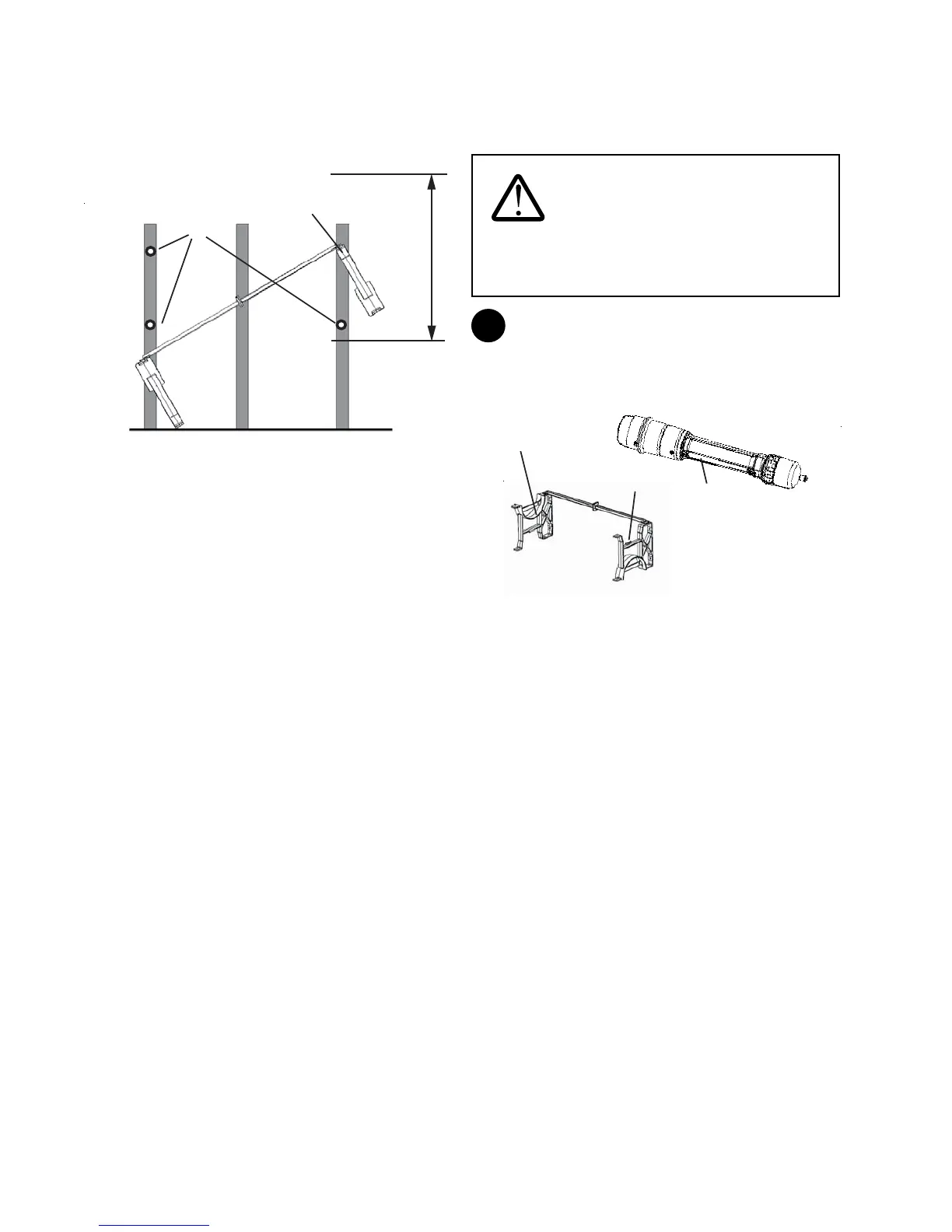
for support, lift the opposite end of the bracket up, align
the top mounting hole on the bracket assembly with the
pre-drilled hole on the wall stud, and secure the bracket
assembly with one 2-1/2" anchoring bolt. Do not tighten
this bolt completely.
Mark mounting hole
locations
Anchor this hole of the Bracket
assembly to the wall stud first
36” Vertical
Clearance
Figure 39
• Swing opposite end of the bracket assembly upward.
Level the bracket. Mark the locations of the remaining
three anchoring bolts with a pen or pencil.
• Lower the unattached end of the bracket assembly back
to the oor.
• Pre-drill the three holes for the remaining three 2-1/2"
anchoring bolts at the marked locations.
• Lift bracket assembly up again, insert the three 2-1/2"
anchoring bolts, and tighten all four anchoring bolts.