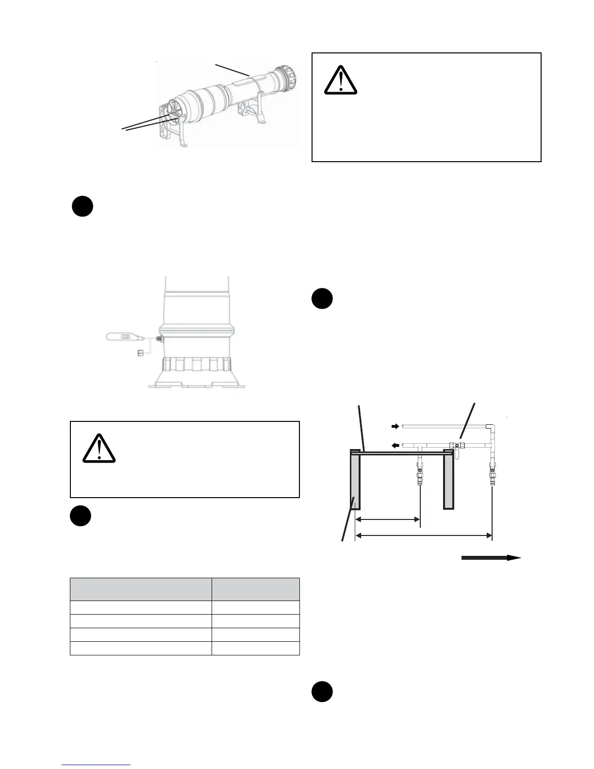
27
Metal
Support
Strap
Fasten
System
to End Cast Iron
Stand here
Figure 41
2
The backpulse tank has been pre-pressurized to
approximately 30-35 psi from the factory. Conrm the
backpulse tank pressure. If the backpulse tank pressure is less
than 30 psi, add air using a pump. Recheck the pressure after
15 minutes to ensure that there are no leaks in the backpulse
tank.
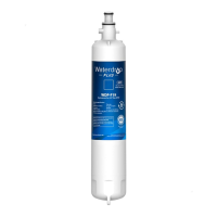
Backpulse
Ta nk
Digital Air
Pressure
Gauge
Valve Cap
Figure 42
WARNING: Be sure to always verify
and set backpulse tank pressure. Homespring must be
empty when checking pressures.
3
The pressure may require adjustment depending on the
water system of the home. Refer to the table below to ensure
proper tank pressure. Air can be added or released from the
air bladder valve as required. Backpulse tank pressure should
be set approximately 5 psi below inlet pressure.
Application/Pump Set-points Backpulse Tank
Pressure
Municipal 30-35 psi (207 kPa)
Pump (20 psi low - 40 psi high) 20 psi (140 kPa)
Pump (30 psi low - 50 psi high) 30 psi (207 kPa)
Pump (40 psi low - 60 psi high) 30-35 psi (207 kPa)
WARNING: Do not pressurize the
backpulse tank to greater than 35 psi. Higher pressures
may cause the tank's bladder to burst, leading to
ineective daily cleaning. Ineective cleaning can
greatly reduce the life of the system, leading to
personal injury, illness, and/or death.
Once the backpulse tank pressure is checked, adjusted, and
set, record nal pressure on the service tag and on Page 3 of
this Manual.
Pipe Assembly and Installation
Ensure that all threaded connections are tted with NSF
approved plumber tape or pipe dope (for potable water) to
prevent leakage.
For systems being installed on surface water applications, the
surface water kit must be installed.
1
Turn o water supply where the water enters the home.
Plumb the inlet pipe at approximately 48" (122 cm) away and
the outlet pipe at approximately 20" (50 cm) away from the
end cast iron stand. Install water shut-o valves on the new
plumbing. The terminal ends of the new plumbing must be a
3/4" MNPT adapter in order to use the supplied stainless steel
ex hoses.
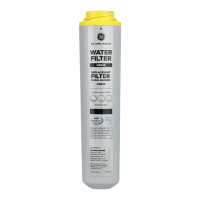
Do not pressurize
Outlet 20”
(51cm)
Bypass Valve
(optional)
Inlet
Valve
Outlet
Valve
Inlet 48”
(122cm)
Horizontal Mounting
Bracket Assembly
System cap will be pointing to the right
End Cast
Iron Stand
Figure 43
Right-pointing system conguration is shown in Figure 43.
For left-pointing system conguration, reverse the horizontal
orientation shown in Figure 43.
NOTE: The water bypass in the gure only bypasses the
system. This conguration may be required according to the
local code in your area.
2
The two inlet/outlet tting assemblies are shipped
pre-assembled, with the mini ball valves and plugs already