28
4
Applicable to Systems in Non-Surface Water
Applications Only:
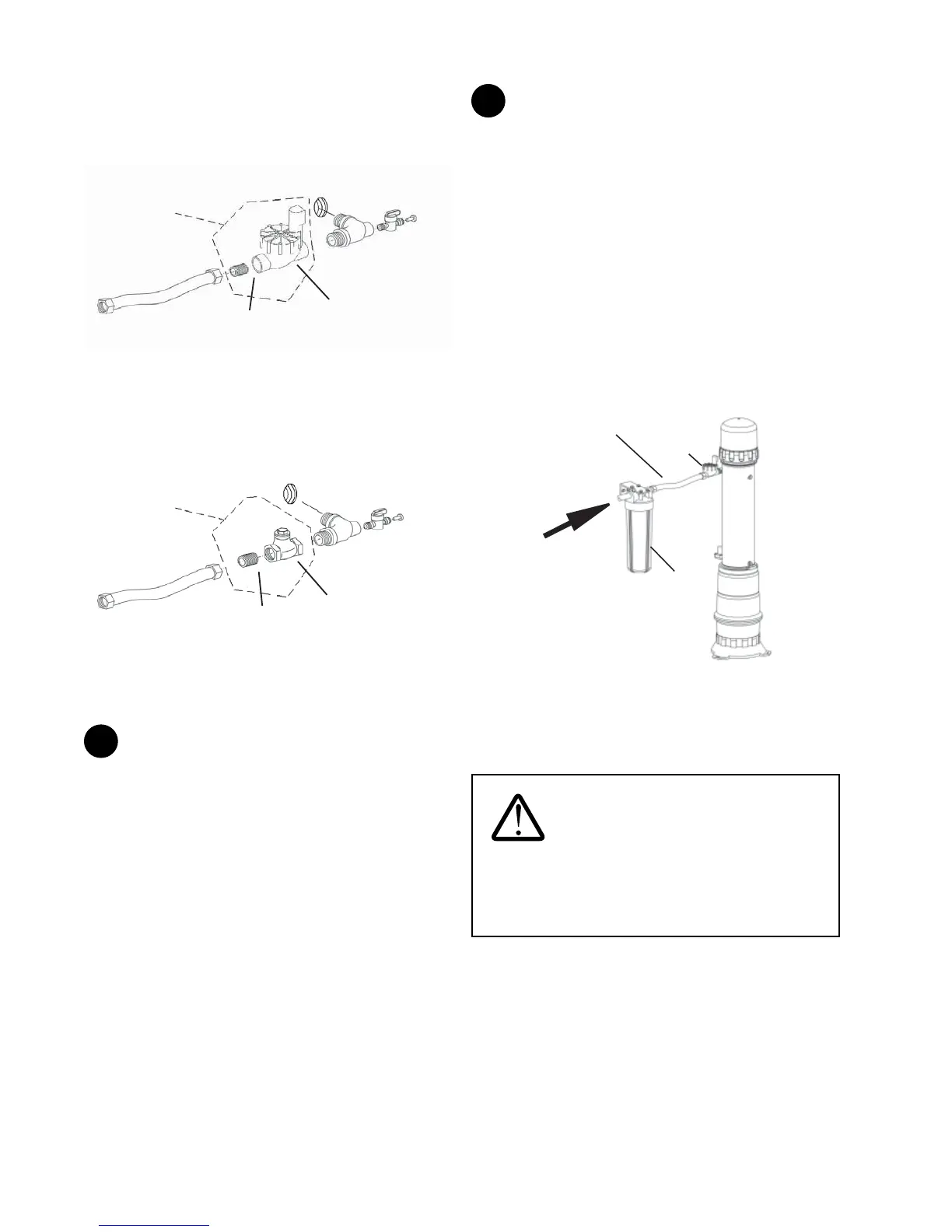
Connect the inlet and outlet tting assemblies to the 3/4"
MNPT ends of the new plumbing with the supplied stainless
steel ex hoses.
Applicable to Systems Equipped with the Surface Water
Option Kit Only:
Select a location on an adjacent wall, with adequate support
(e.g. wall studs), between the stainless steel ex hose of the
inlet tting assembly and the inlet line of the new plumbing.
Follow the instructions described under the Surface Water
Option Kit Installation section in this manual to install the
external prelter. Connect the stainless steel ex hose on the
inlet tting assembly to the external prelter. Once nished,
connect the external prelter to the 3/4" MNPT end of the new
inlet plumbing.
External
Prefilter
Inlet
Solenoid
Valve
To ¾” MNPT end of
the new Inlet
plumbing
Stainless Steel
Flex Hose
Figure 46
Connect the stainless steel ex hose of the outlet tting
assembly to the 3/4" MNPT end of the new outlet plumbing.
For rotate the inlet solenoid valve right-side-up.
WARNING: Use only supplied inlet
and outlet ttings. Only plastic ttings can be installed
in the Homespring.
Surface Water Kit not recommended on horizontal
installations.
NOTE: Ensure that all threaded connections are tted with
plumber tape or pipe dope (for potable water) to prevent
leakage.
installed. Ensure that the plumber tape at both threaded ends
are in good condition. Assemble the inlet and outlet tting
assemblies as shown.
Inlet Fitting Assembly
Mini Ball Valve
with Plug
Inlet/Outlet
Fitting
Stainless Steel
Flex Hose
For models
equipped with
Surface Water
Option Kit only
Inlet Solenoid
Valve
3/4” MNPT
Nipple
Inlet port of
System
Figure 44
The directional arrow on the inlet solenoid valve must point in
the direction of the water ow.
Outlet Fitting Assembly
Mini Ball Valve
with Plug
Inlet/Outlet
Fitting
Stainless Steel
Flex Hose
For models
equipped with
Surface Water
Option Kit only
3/4” MNPT
Nipple
Check
Valve
of System
Figure 45
The directional arrow on the check valve must point in the
direction of the water ow.
3
Install the drain solenoid valve (normally closed) to the
1/2" nipple to the drain port of the system. The directional on
the drain solenoid valve must point in the direction of the
water ow (i.e. away from the system). Install the nylon elbow
to the ow exit port of the drain solenoid valve.
Install the 1/2" nipple and the 1/2" brass elbow provided in the
horizontal mounting kit at the drain port of the system. Install
the drain solenoid valve to the 1/2" brass elbow using another
1/2" nipple.