29
5
Inlet Fitting Assembly:
Follow the instructions in the Pipe Assembly and Installation
section to assemble the inlet tting assembly. If the surface
water option kit is installed, rotate the inlet solenoid valve
right-side-up.
Drain Line Assembly:
Install the 1/2" nipple and the 1/2" brass elbow provided in the
horizontal mounting kit to the drain port of the system. Install
the drain solenoid valve to the 1/2" brass elbow using another
1/2" nipple. Thread the nylon elbow to the water ow exit port
of the drain solenoid valve. Follow instructions in the Final
Plumbing Assembly section to nish the drain line assembly.
½” Nipple
½” Nipple
½” Brass
Elbow
Nylon
Elbow
Drain
Solenoid
Valve
Drain Port
Figure 47
Air Vent Assemblies:
A. Using a 1/4" hex key, unscrew the two black plastic plugs
on the system casing. The two plugs should be facing
upward when the system is installed on the bracket.
B. Complete the bre chamber air vent assembly as shown in
Figure 48. Use plumber tape at all connections.
Air Relief Valve
¼” Brass Coupling
6” long PVC nipple
Figure 48
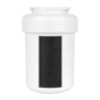
Install ber chamber air vent assembly on the 1/4" NPT
port close to the backpulse tank (Figure 49). Do not use
tools and do not over-tighten the connection. Take care
not to cross-thread this connection.
Backpulse Tank
Remove black
plug at this ¼” NPT
port before
installing Air Vent
Assembly
Fibre Chamber
Air Vent Assembly
Figure 49
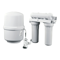
C. Complete pre-lter chamber air vent assembly as shown
in Figure 50. A second air relief valve is provided with the
central water ltration system. Use plumber tape on all
connections.
Air Relief
¼” BrassTee
2” long
¼” x ½”
PVC Nipple
Reducer Elbrow
Valve
¼” Polypropylene Nipple
½” Brass Plug
Figure 50
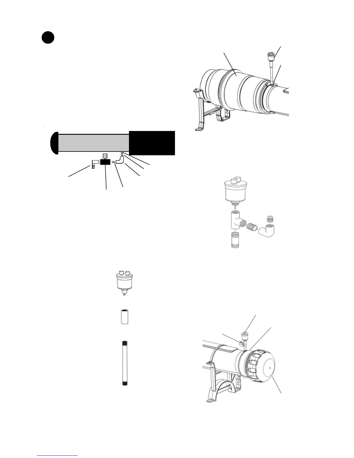
Install the pre-lter air vent assembly on the 1/4" NPT
port close to the system cap. Do not use tools and do not
overtighten this connection. Take care not to cross-thread
this connection.
Ensure that the 1/2" brass plug is at an accessible
orientation (i.e. not facing the wall).
System Cap
½” Brass plug
Pre-filter Chamber Air Vent Assembly
Remove black plug
at this ¼” NPT port
before installing
Air Vent Assembly
Figure 51
 Loading...