51
Follow steps 18 to 34 for horizontally-mounted systems:
Air Relief
Valve
System
Cap
Metal
Support
Strap
Air Vent
Assembly
System
Casing
Backpulse
Tank
End Cast
Iron Stand
Locking
Clip
Locking
Clip screw
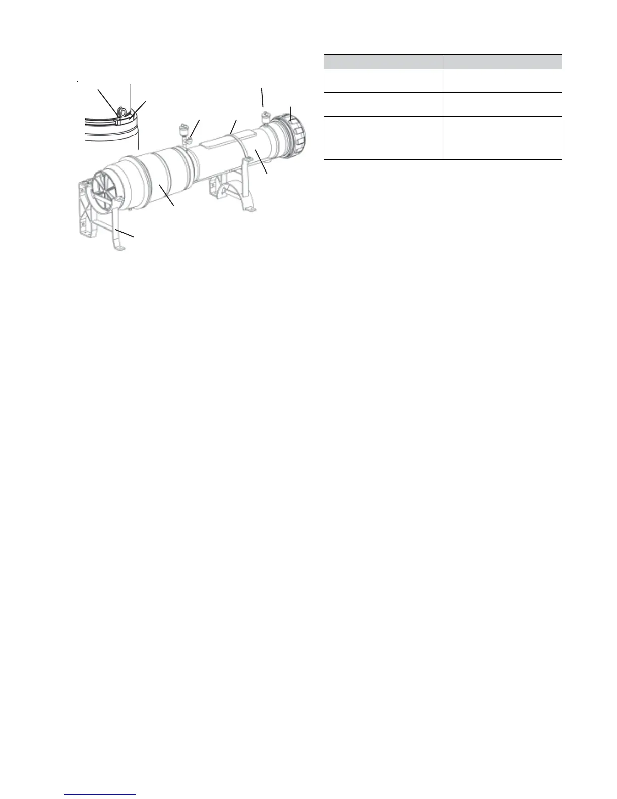
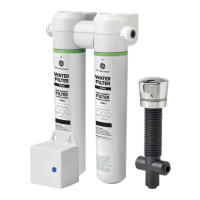
Figure 84
17. Attach a 1/4” tubing to the inlet mini ball and direct the
other end to a large pail. Open the mini ball valve to drain
the water inside the internal prelter cavity.
18. Remove the 1/4” tubing from the mini ball valve.
19. Remove the metal support strap.
20. Remove the air relief valve, the air vent assembly, the
inlet pipe assembly, the outlet pipe assembly, and the
drain line assembly from the system. Removal of the inlet
pipe assembly and the outlet pipe assembly may require
disconnecting the inlet line and outlet line at multiple
places.
21. Using the cap wrench, remove the system cap.
22. Unscrew the locking clip screw and remove the locking
clip.
23. Using a strap wrench, loosen the system casing from the
backpulse tank. Do not detach the system casing from
the backpulse tank completely.
24. Unscrew the two bolts securing the bottom of the
backpulse tank to the end cast iron stand.
25. Remove the entire system from the horizontal mounting
bracket and stand the system upright on the oor.
26. Remove all the inlet, drain, and air relief valve plugs from
the new system and insert those plugs into the equivalent
ports of the old system.
27. Remove the internal prelter from the system. Set the
internal prelter aside in a clean area for possible reuse.
28. Unscrew the system casing from the backpulse tank.
29. If under warranty, the old system must be completely
sealed, packaged and returned to the factory within
24 hours to avoid internal damage and allow a cause
analysis to be completed.
30. Label the box appropriately as in the table below. Call the
Homespring Consumer products Customer Service for
shipping and handling details at 1-800-279-9404.
Label on System Box Use only if:
“INTEGRITY” + Homespring
Certied Technician Number
If the system has failed the
integrity test.
“FOULED” + Homespring
Certied Technician Number
If the system is fouled.
“DAMAGED” + Homespring
Certied Technician Number
If the system has been
damaged during transportation,
warehousing or installation
steps.
31. Partially screw the new system casing on the backpulse
tank by hand. Do not use a strap wrench on models with
a stainless steel facade.
32. Lift and place the system on the horizontal mounting
bracket. Reattach the backpulse tank to the end cast iron
stand. Once nished, tighten the system casing on the
backpulse tank by the hand.
33. Reattach the locking clip, air relief valve, inlet/outlet/
drain pipe assemblies, internal prelter, system cap,
external prelter (if applicable), and the air vent assembly.
Reattach the metal support strap and the controller. Refer
to E. INSTALLATION INSTRUCTIONS.
34. Reconnect the system to the house plumbing and the
drain. Follow COMMISSIONING to start up the system
again.
B. O-RING REPLACEMENT
The O-ring may require a replacement if there is a leak
between the System Cap and the System.
Replacement Instructions:
1. Close the inlet valve.
2. Depressurize the system by performing a manual ush
sequence. Refer to the instructions in the Controller
Functions section for how to perform a manual ush
sequence.
For Horizontally-mounted Systems, connect a 1/4" tubing
to the inlet mini ball valve, direct the other end of the 1/4"
tubing to a drain or a pail, and open the inlet mini ball
valve to drain the water in the internal prelter cavity.
3. Using the cap wrench, remove the system cap.
4. Carefully remove the O-ring from the system.
5. Clean the O-ring with a clean, soft cloth. Check for nicks,
pits, proper formation and cleanliness.
6. If nothing appears unusual, apply a very small amount
of DOW CORNING 111 silicone lubricant to the O-ring
and reinstall the O-ring. If the O-ring appears damaged,
replace the O-ring with a new O-ring.
7. Replace system cap tightly using the cap wrench.
8. Open the inlet valve slowly.