INSTALLATION AND OPERATION
SX TRANSISTOR CONTROL Page 1
Note: The information contained herein is intended
to assist OEM's, Dealers and Users of electric vehicles in
the application, installation and service of GE solid-state controllers. This manual does not purport to cover all
variations in OEM vehicle types. Nor does it provide for every possible contingency to be met involving vehicle
installation, operation or maintenance. For additional information and/or problem resolution, please refer the matter to
the OEM vehicle manufacturer through his normal field service channels. Do not contact GE directly for this
assistance.
General Electric Company October 2005
Section 1.0 INTRODUCTION .................................................................................................................. 3
1.1 Motor Characteristics ........................................................................................ 3
1.2 Solid-State Reversing ........................................................................................ 4
1.3 Flexible System Application ............................................................................... 4
1.4 More Features with Fewer Components ........................................................... 4
Section 2.0 FEATURES OF SX FAMILY OF MOTOR CONTROLLERS ............................................... 4
2.1 Performance ...................................................................................................... 4
2.1.1 Oscillator Card Features ............................................................................. 4
2.1.1.a Standard Operation..................................................................................... 4
2.1.1.b Control Acceleration ................................................................................... 5
2.1.2 Current Limit ............................................................................................... 5
2.1.3 Regenerative Braking to Base Speed ......................................................... 5
2.1.4 Auxiliary Speed Control ............................................................................... 5
2.1.4.a Field Weakening......................................................................................... 5
2.1.4.b Speed Limits .............................................................................................. 5
2.1.4.c Top Speed Regulation .................................................................................5
2.1.5 Ramp Start .................................................................................................. 5
2.1.6 On-Board Coil Drivers and Internal Coil Suppression ................................ 6
2.2 System Protective Override ............................................................................... 6
2.2.1 Static Return to Off (SRO) ......................................................................... 6
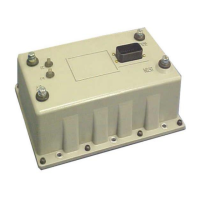
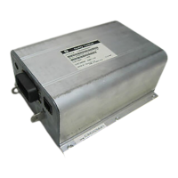
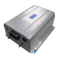
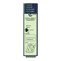
SEPARATELY EXCITED (SX) TRANSISTORIZED MOTOR
CONTROLLERS
FOR NEIGHBORHOOD ELECTRIC VEHICLE APPLICATIONS
INSTALLATION AND OPERATION MANUAL
GE MODEL IC3645SR7A353T4
Updated Sept 2019


 Loading...