Auxiliary Drive to ISBus Interface Board IS200ADII GEI-100305
14
Table 14. P2 Connector, RJ45 ISBus TX/OUT
Pin No. Nomenclature Description
1, 2 NC Not connected
3 ISBTXP ISBus transmit positive
4, 5 NC Not connected
6 ISBTXN ISBus transmit negative
7, 8 NC Not connected
9, 10 Shield Shield connection
Installation and Renewal/Warranty Replacement
How to Order a Board
When ordering a replacement board for a GE drive, you need to know:
• How to accurately identify the part
• If the part is under warranty
• How to place the order
This information helps ensure that GE can process the order accurately and as soon
as possible.
Board Identification
A printed wiring board is identified by an alphanumeric part (catalog) number
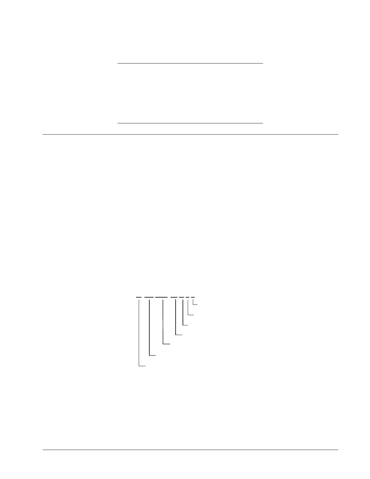
located near its edge. Figure 3 explains the structure of the part number.
The board’s functional acronym, shown in Figure 3, is normally based on the board
description, or name. For example, the ADII board is described as the Auxiliary
Drive to ISBus Interface board.
IS 200 ADII H# A A A
1
Backward compatible
2
Not backward compatible
3
200 indicates a base-level board; 215 indicates a
higher-level assembly or added components (such
as PROM)
Manufacturer (DS & IS for GE in Salem, VA)
Assembly level
3
Functional acronym
Group (variation, G or H)
Functional revision
2
Functional revision
1
Artwork revision
1
Figure 3. Board Part Number Conventions

 Loading...


