Installation InstrUctions
i ii i i i
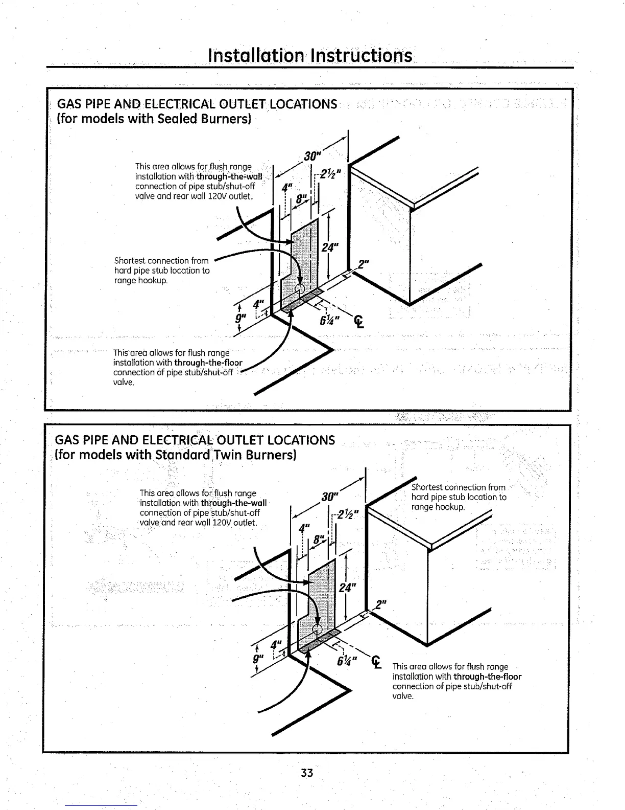
GAS PIPE AND .ELECTRICAL OUTLET LOCATIONS
(for models with Sealed Burners)
This area allows for flush range
installation with through;the÷wall
connection of pipe stub/shut-off
valve and rear wall 120Voutlet.
Shortest connection from
hard pipe stub location to
range hookup.
This area allows for flush range
installation with thraugh-theTfloor
connection of pipe stub/shut-off
valve.
_ ._]°' ...... .... :: -
,...., ,r
GAS PIPE AND ELECTRICAL OUTLET LOCATIONS
(for models with Standard Twin Burners)
This area allows for flush range
installation with through-the-wall
connection of pipe stub/shut-off
valve and rear wall 120V outlet.
.=ctionfrom
hard pipe stub location to
range hookup.
This area allows for flush range
installation with through-the-floor
connection of pipe stub!shut-off
valve.
33
 Loading...