A2
A1
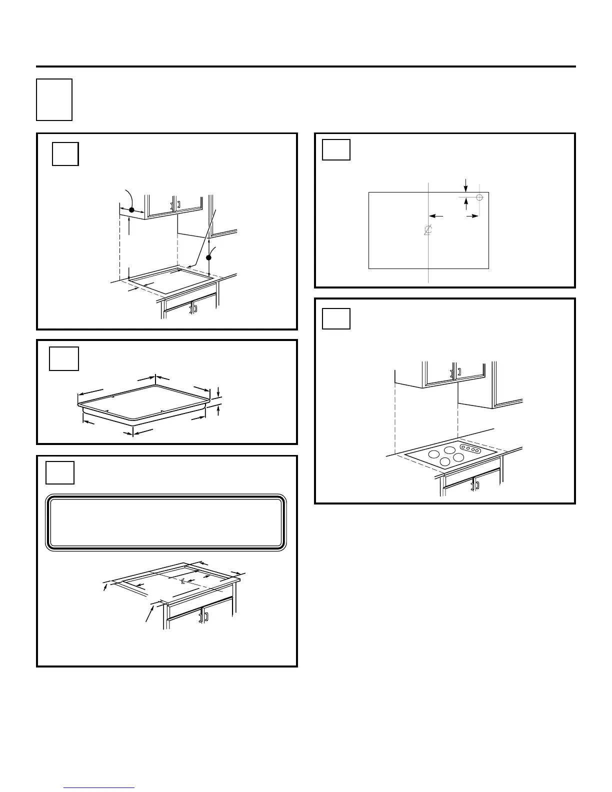
The following MINIMUM clearance
dimensions must be maintained.
A3
To insure accuracy, it is best to make
a template when cutting the opening
in the counter.
A4
The recommended Gas Supply
Location from the backwall.
Overall cooktop dimensions
Cutout dimensions of the
countertop
4
Installation Instructions
COOKTOP
30"
21"
19 3/8"
28 1/4"
3"
2 1/4" Min.
Between cutout
and the wall behind
the cooktop
19 5/8" width of cut
28 1/2"
length of
cut
2 1/2"Min.
from front edge
of cutout
and front edge
of countertop
14 1/4"
A5
Make sure the wall coverings,
countertop and cabinets around the
cooktop can withstand heat (up to
200°F) generated by cooktop.
13 1/4"
From Cutout
Center Line
1"Min. From Backwall
Recommended
gas supply
location.
Wall covering,
cabinets and
countertop
must withstand
heat up to 200°F.
3 3/4" MIN.
clearance from
cutout to side
wall on the left
of the unit
30" MIN.
clearance from
countertop to
unprotected
overhead surface
3 3/4 MIN.
clearance from
cutout to side
wall on the right
of the unit
13" MAX. Depth
of unprotected
overhead cabinets
18" MIN.
height from
countertop to
nearest cabinet on
either side of unit
3 3/4" MIN.
2 1/2" Min.
1" Min. from Backwall
PREPARING THE OPENING
A
 Loading...