– 41 –
7R$FFHVV,Q¿QLWH+HDW6ZLWFKHVDQGLED Display
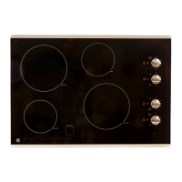
1. Remove four 1/4 in. hex head screws from the
switch bracket.
NOTE: The cooktop is resting on the shafts of the
switches. When these screws are removed, the
cooktop can lower onto a protected surface.
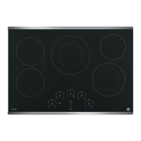
2. Rotate the bracket to access the display and the
neon indicators.
NOTE: Grommets shown below are pushed through
the glass cooktop.
On parts look-up, the grommets are shown between
the bracket and display.
3. The LED Boards and housing assembly clip over
the switch plate, and also support the neon
indicators.
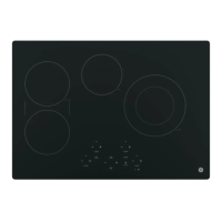
4. To remove the LED assembly, each neon
indicator has to be released with a small
screwdriver.
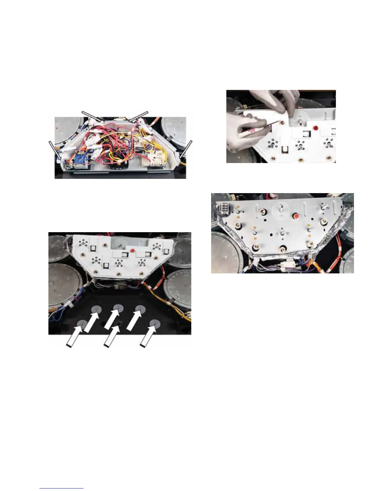
5. With the assembly removed, the screws for the
LQ¿QLWHKHDWVZLWFKHVDUHDFFHVVLEOH
 Loading...