30” RADIANT SLIDE-IN CONVECTION RANGE
SURFACE UNIT SWITCHES
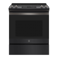
RADIANT HEATING ELEMENT SYSTEMS
Heating Elements: The radiant heating element consists of a resistance
ULEERQDWWDFKHGWRPLFURSRURXVLQVXODWLRQZLWKPROGHGFHUDPLF¿EHUZDOOVLQ
a corrosion-protected metal tray.
The Heating Elements come in four sizes:
• 6” – 240 Volt, 1200 Watts
• 9”/6” – 240 Volt, 3100 Watts
• 12”/9” – 240 Volt, 3000 Watts
• Warmer – 240 Volt, 120 Watts
CONTROL PANEL ASSEMBLY
5HSODFLQJ,Q¿QLWH6ZLWFKHV
1. Remove the two screws holding the
LQ¿QLWHVZLWFK
2. Remove steel control panel insert by
UHPRYLQJVFUHZV
3. From the rear of the control panel
assembly, unplug wires and remove
LQ¿QLWHVZLWFK
4. Repeat steps in reverse order to
UHDVVHPEOHWKHXQLW
Removing Faceplate
1.7XUQWKHSRZHURႇWRWKHXQLW
2.5HPRYHDOONQREV
3. Unscrew all faceplate retainers while
holding the faceplate against the
FRQWUROWULP7KHUHWDLQHUVPXVWRQO\
EHKDQGWLJKWHQHG
4. Move the faceplate 3 inches away
from the control panel and unplug the
KDUQHVVIURPWKHSDQHO
5. Repeat steps in reverse order to
UHDVVHPEOHWKHXQLW
NOTE: Installation
information is for reference
only. See Installation
Instructions shipped with
the product for complete
details and before
attempting to install.
Bracket should be
DWWDFKHGWRWKHÀRRURUZDOO
to hold either the right or
left rear leveling leg. Make
sure the leveling leg re-engages the bracket when the range is moved for any reason.
TEMPERATURE LIMIT/HOT LIGHT SWITCH
The Temperature Limit/Hot Light Switch performs two functions:
1. Turns on HOT LIGHT DVVRRQDVJODVVWHPSHUDWXUHUHDFKHV)7KHHOT LIGHT
will remain on until the glass surface above the heating unit has cooled below 150°F
HYHQDIWHUVXUIDFHXQLWVZLWFKKDVEHHQWXUQHGRႇ
2. Detects when glass temperature above a unit has exceeded its limit of approximately
)DQGGLVFRQQHFWVSRZHUWRWKDWXQLW:KHQJODVVWHPSHUDWXUHFRROVEHORZ
)WKHXQLWZLOOWXUQEDFNRQ
The Temperature Limit/Hot Light Switch cannot be calibrated.
REMOVABLE OVEN DOOR
COMPONENT COMPARTMENT AIRFLOW
The oven uses a fan for cooling the components. Air is pulled in by the fan blades
and circulated in the component compartment. The air is exhausted through
louvers below the control panel and out the slots above the door.
DOOR ASSEMBLIES:
The doors can be separated into two assemblies: (1) Outer assembly which
consists of handle, vent trim, outer glass, bottom trim and frame; (2) Inner
assembly which consists of inner panel, gasket, glass panels and insulation.
The assemblies are held together by 2 screws on each side, along with 4 screws
across the bottom.
CAUTION
Care must be taken when mounting door handle not to
overtighten handle screws. Overtightening screws can damage handle. Hand-
WLJKWHQVFUHZVGRQRWXVHHOHFWULFGULYHU0DNHVXUHKDQGOH¿WVVQXJJO\WRGRRU
panel.
SELF-CLEAN DOOR GASKET: The door gasket is attached to the inner door panel
E\DFKDLQRIVSULQJFOLSV
1. /RFDWHVSULQJFOLSDWFHQWHURIJDVNHWDQGLQVHUWLQKROHRQLQQHUGRRUSDQHOQHDUWRS
2. ,QVWDOOJDVNHWE\EHQGLQJDWEHVLGHFOLSDQGURFNLQJLQWRKROH
3. 7XFNORRVHHQGVLQWRVORWDWWKHERWWRPRILQQHUSDQHO
REMOVABLE OVEN DOOR
The door is very heavy. Be careful when removing
and lifting the door. Do not lift the door by the handle.
To Remove:
1. )XOO\RSHQWKHGRRU
2. Push the hinge locks down toward the door frame,
WRWKHXQORFNHGSRVLWLRQ$WRROVXFKDVDVPDOO
ÀDWEODGHVFUHZGULYHUPD\EHUHTXLUHG
3.)LUPO\JUDVSERWKVLGHVRIWKHGRRUDWWKHWRS
To Replace:
1. Firmly grasp both sides of the door at
WKHWRS
2. With the door at the same angle as the
removal position, seat the indentation of
the hinge arm into the bottom edge of the
KLQJHVORW7KHQRWFKLQWKHKLQJHDUPPXVW
EHIXOO\VHDWHGLQWRWKHERWWRPRIWKHVORW
Removal position
Push hinge locks up to lock
3. )XOO\RSHQWKHGRRU,IWKHGRRUZLOOQRWIXOO\RSHQ
the indentation is not seated correctly in the bot-
WRPHGJHRIWKHVORW
4. Push the hinge locks up against the front frame of
WKHRYHQFDYLW\WRWKHORFNHGSRVLWLRQ
5. &ORVHWKHRYHQGRRU
4. Close door to the door removal position, which is halfway
EHWZHHQWKHEURLOVWRSSRVLWLRQDQGIXOO\FORVHG
5./LIWGRRUXSXQWLOWKHKLQJHDUPLVFOHDURIWKHVORW
Bottom Edge
of Slot
Hinge Arm
Indentation
Hinge Arm
Screw Must
Enter Wood or
Metal
Anti-Tip Bracket
Attachment to Wall or Floor
Hinge
Lock
Wall
Plate
Adjacent Cabinet or Final
Location of Range Side Panel
Wood Floor Holes
Anti-Tip Bracket Side
Rear Leveling
Leg of Range
Concrete Floor Holes
Wall Holes
Slot
Hinge Lock
Pull hinge locks down to unlock
OVEN SENSOR AND DOOR SWITCH OHMMETER TEST
(See “Motorized Door Lock Operation” for door switch function explanation.)
Remove power from oven. Make resistance measurement from side of sensor
and lock switch connector, with exposed terminals disconnected from
control.
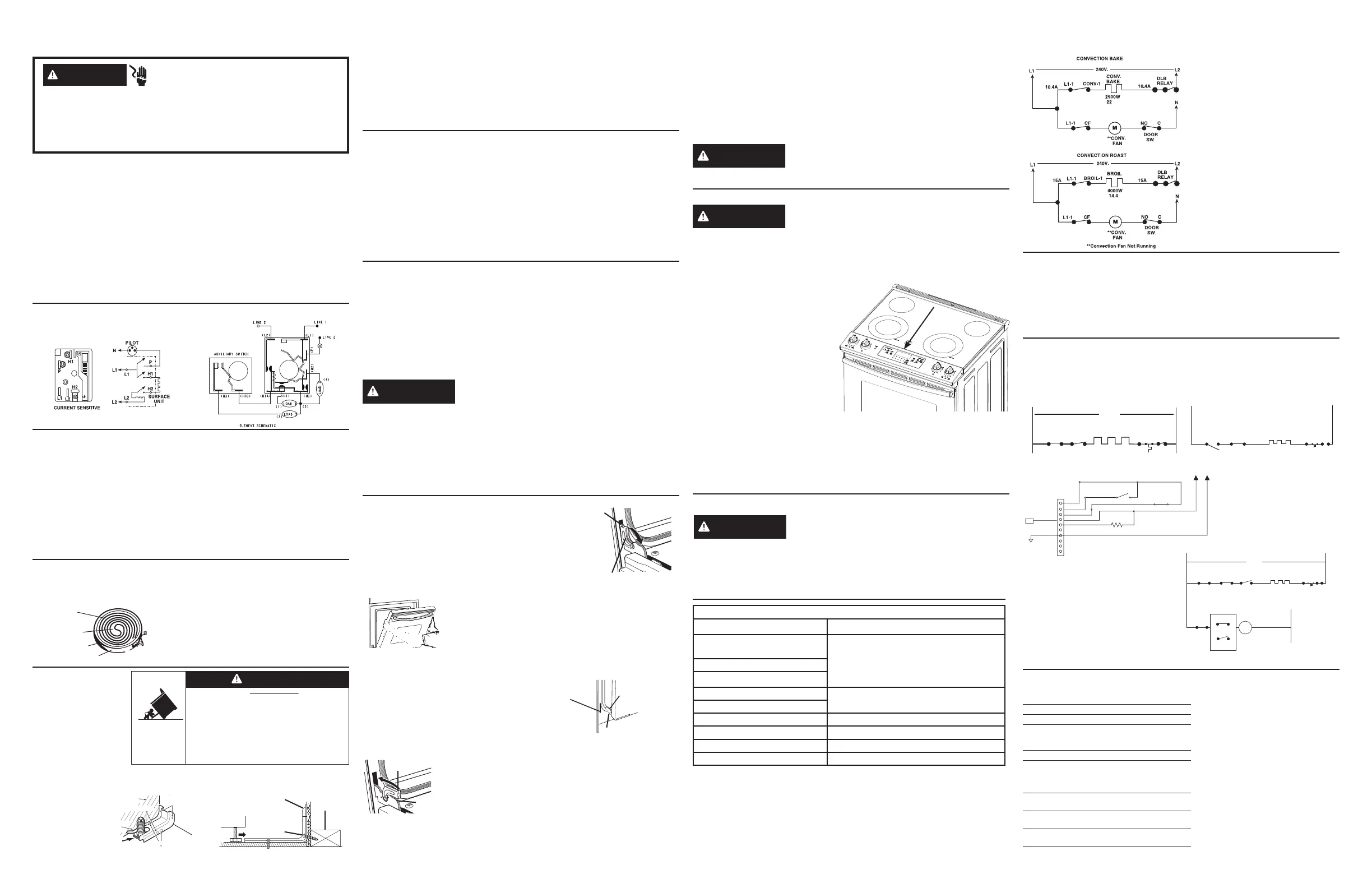
**If convection fan is not working,
make the following checks:
• Check the voltage from terminal CF
to N on control—it should read 120V
in Conv Bake or Roast mode. If not,
replace the control.
• If voltage is OK, check the
convection fan motor. It reads
approximately 15–20 at room
temperature. Check to make sure the
fan shaft is not rubbing on the oven
liner.
Heating Element
Micro Porous
Insulation
Ceramic Fiber
Molded Walls
Metal Tray
SH. 1 of 4 31-17264
WARNING
Electrical Shock Hazard
'HDWKRUVHULRXVLQMXU\FDQUHVXOWIURPIDLOXUHWRIROORZWKHVHLQVWUXFWLRQV
6HUYLFHE\DTXDOL¿HGVHUYLFHWHFKQLFLDQRQO\
'LVFRQQHFWSRZHUEHIRUHVHUYLFLQJWKLVSURGXFW
5HFRQQHFWDOOJURXQGLQJGHYLFHVDIWHUVHUYLFH
5HSODFHDOOSDUWVDQGSDQHOVEHIRUHRSHUDWLQJ
A child or adult can tip the range and be killed.
Verify the anti-tip bracket has been properly
installed and engaged.
Ensure the anti-tip bracket is re-engaged when
the range is moved.
Do not operate the range without the anti-tip bracket
in place and engaged.
Failure to follow these instructions can result in
death or serious burns to children or adults.
Tip-Over Hazard
WARNING
CONTROL PANEL ASSEMBLY AND REMOVAL
The control panel contains the Main Logic Board, burner cooktop touch boards and
RYHQWRXFKERDUG
To service:
5HPRYHWKHVFUHZVIURPVLGHVHFXULQJWKHFRQWUROSDQHODVVHPEO\WRWKH
FRQWUROHQFORVXUH
/LIWWKHSDQHODQGGLVFRQQHFWWKHZLULQJKDUQHVVWRUHPRYH
/D\WKHSDQHODVVHPEO\RQWKHFRRNLQJVXUIDFH
5HYHUVHWKHSURFHVVWRLQVWDOO
WARNING
3ODFHDSURWHFWLYHFRYHULQJVXFKDVDWRZHOEHWZHHQWKH
FRQWUROSDQHODQGWKHFRRNLQJVXUIDFHWRDYRLGGDPDJHWRWKHFRQWUROSDQHO
COOKTOP REMOVAL
CAUTION
5DLVLQJWKHFRRNWRSWRRKLJKFDQEUHDNWKHJODVV
To Remove:
1.'LVFRQQHFWWKHSRZHU
2.5HPRYHWKHVFUHZVIURPVLGHVVHFXULQJWKHFRQWUROSDQHODVVHPEO\WRWKH
SODVWLFORZHUWULP
3.7RGLVHQJDJHWKHVQDS¿WRIWKHFRQWUROSDQHODVVHPEO\WRWKHSODVWLFORZHUWULPGR
the following:
8VLQJD´SXWW\NQLIH¿UPO\
press the center of the plastic lower
trim at the maintop contact point
towards the control panel assembly
XQWLOLWGLVFRQQHFWV
4. Unplug the wiring connections
that connect to the enclosure and
XQVFUHZWKHJURXQGZLUH
5. Unplug the remaining connections
from the main harness that connects
WRWKHFRQWUROSDQHODVVHPEO\6HW
WKHFRQWUROSDQHODVLGH
6. Remove 6 screws securing the plastic lower trim to the maintop frame and remove
LW
7.5HPRYHVFUHZVVHFXULQJWKHFRQWUROHQFORVXUHWRWKHPDLQWRSIUDPH
8./LIWWKHFRRNWRSDWWKHIURQWDQGSXOOIRUZDUG
9.'LVFRQQHFWWKHZLULQJKDUQHVVDWWKHUHDURIWKHPDLQWRS
5HYHUVHWKHSURFHVVWRUHLQVWDOO
DISCONNECT POWER BEFORE SERVICING
IMPORTANT: Reconnect all grounding devices. All parts of this appliance capable
of conducting electrical current are grounded. If grounding wires, screws, straps,
clips, nuts or washers used to complete a path to ground are removed for service,
they must be returned to their original position and properly fastened.
GROUNDING SPECIFICATIONS
*URXQG3DWK5HVLVWDQFH
0D[
Insulation Resistance 250K
0LQ
INSTALLATION REQUIREMENTS
Power Supply:7KLVDSSOLDQFHPXVWEHVXSSOLHGZLWKSURSHUYROWDJHDQGIUHTXHQF\
and connected to an individual properly grounded branch circuit, protected by a circuit
EUHDNHURUWLPHGHOD\IXVHDVQRWHGRQUDWLQJSODWH:LULQJPXVWFRQIRUPWRWKH1DWLRQDO
(OHFWULFDO&RGHV7KHUDWLQJSODWHLVORFDWHGRQORZHUIURQWIUDPHEHKLQGWKHVWRUDJH
GUDZHU
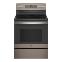
DUAL CIRCUIT CONTROL
This element has two cooking zones:
• To use the large cooking area, push to turn the control knob clockwise to the
GHVLUHGVHWWLQJ
• To use the small cooking area, push to turn the control knob counterclockwise to the
GHVLUHGVHWWLQJ
When a cooking zone is activated, coils beneath the zone radiate heat through the
JODVVFRRNWRSWRWKHXWHQVLO7KHUHGJORZRIWKHFRLOVZLOOEHYLVLEOHWKURXJKWKHJODVV
,WZLOOWDNHWKHFRRNLQJ]RQHRQWKHJODVVVXUIDFHDIHZPRPHQWVWRKHDWXS7KHFRLO
F\FOHVRQDQGRႇWRPDLQWDLQWKHVHOHFWHGVHWWLQJ
ELECTRONIC OVEN CONTROL
CAUTION
Components are electrically HOT on control when
voltage is connected to oven. The Electronic Oven Control system consists
of the control, key panel, oven sensor, door and lock assembly.
NOTE:7HPSHUDWXUH0RGH6HOHFWLRQQHFHVVDU\IRURSHUDWLRQRI5HOD\FRQWDFWV
VOLTAGE MUST BE PRESENT ACROSS TERMINALS L1 TO N FOR CON-
TROL TO OPERATE.
CONTROL VOLTAGE
Terminals Voltage
%URLO&20SLQWR47+12
SLQ
9$&DOOWKHWLPH
/WR1
/WR1
/WR%$.( 9$&ZKHQFRRNLQJPRGHLVDFWLYHDQG
oven is not calling for heat
L1 to BROIL
-WR1 9$&ZKHQIDQLVWXUQLQJ&&:
-WR1 9$&ZKHQIDQLVWXUQLQJ&:
-WR1 9$&ZKHQOLJKWLVRQ
-WR1 9$&ORFNLQJRUXQORFNLQJ
2YHQOLJKWQRWZRUNLQJ0DNHWKHIROORZLQJFKHFNV
&KHFNRYHQOLJKWEXOE
/LJKWLVWRFRPHRQZKHQGRRULVRSHQHG²FKHFNYROWDJHDFURVVOLJKWVRFNHW
7HUPLQDOVVKRXOGUHDG9$&,IYROWVFKHFNMDPEVZLWFKDQGZLULQJ
• /LJKWLVWRFRPHRQZKHQFRQWUROOLJKWSDGLVSUHVVHGK906VKRXOGFOLFN&KHFN
voltage from
J903
WR16KRXOGUHDG9$&,IYROWVUHSODFHFRQWURO
ELECTRONIC OVEN CONTROL (Cont)
THERMAL CUT-OUTS
THERMAL CUTOUT SWITCH
$RQHVKRWWKHUPDOIXVHLVPRXQWHGWRWKHUHDURIWKHRYHQ7KHVZLWFKZLOO
open the L2 leg of the power to the heating elements in the event of an over-
WHPSHUDWXUHFRQGLWLRQ7KHVZLWFKZLOORSHQZKHQWKHSDQHOLWLVPRXQWHGWR
UHDFKHVDSSUR[LPDWHO\)DQGZLOOQRWUHVHW7KHRYHQZLOOQRWKHDWDIWHUWKH
VZLWFKRSHQVDQGWKHVZLWFKZLOOQHHGWREHUHSODFHG
V
J401
RTD1
Oven Sensor and Lock Switch Connector
10
Door Plunger
YR
YR
Door Lock
MOTOR SWITCH
YR
5 V-Splice
GND
OX
VX
NW
WX
"L1" BLACK
CONV BAKE
L1
"L2" RED
BAKE
RLY
BROIL
RLY
BAKE
2850 W
240 V
TCO
14.2A
DBL
RLY
“L1” BLACK
L1
L1
K902
RLY
DLB
RLY
BROIL RLY BAKE RLY CONV RLY
CONVECTION
CONV FAN
2500 W
10.42 A
TCO
CW
M
N
CCW
240 V
CONVECTION
CONV FAN RLY
“L2” RED
BROIL AND CLEAN UNTIL AFTER 750 F IS REACHED
“L1” BLACK
L1 BR
TCO
16.7 A
BROIL
40000 W
“L2” RED
DLB
RELAY
QTH
RELAY
BROIL
RELAY
CONTROL VOLTAGE
TERMINALS VOLTAGE
L1-N 120VAC ALL THE TIME
L2-N 120 VAC ALL THE TIME
L1-L2 240 VOLTS when oven is not calling for
heat (BAKE, CONV., and BROIL relay
contacts open).
CN600-7-N 120 VOLTS when light is on.
CN600-1-N 120 VOLTS not locking or unlocking, door
closed
CIRCUIT TERMINALS OHMS
2YHQVHQVRU ȍ#5P7HPS
ȍ#)
Door Unlatched 1-2 open
and open 1-3 open
'RRU/DWFKHG ȍ
DQGFORVHG ȍ
*If oven light is not working, make
the following checks:
• Check oven light bulb.
• Light is to come on when door is
opened–check voltage across light
socket terminals; voltage should
read 120 VAC. If 0 volts, check
jamb switch and wiring.
• Light is to come on when control
light pad is pressed. K906 should
click–check voltage from J703-1
to Neutral. Voltage should read
120 VAC. If 0 volts, check oven
light keypad using ohmmeter test.
If keypad is good, replace the
control.
 Loading...