EasyManua.ls Logo

GE JX1827CB User Manual

GE JX1827CB
4 pages
To Next Page IconTo Next Page
Page #1 background imageLoading...
Page #1 background image
PART QUANTITY
Trim Frame 1
Bottom Duct 1
Side Duct 1
1” Screws 6
(4 required, 2 extra)
1/2” Screws 15
(11 required, 4 extra)
Anti-Tip Bracket 1
Bottom Bracket 1
Upper Duct 1
Template 1
PARTS INCLUDED
Questions? Call GE Answer Center at 800.626.2000
or Visit our Website at:
www.GEAppliances.com
READ CAREFULLY.
KEEP THESE INSTRUCTIONS
.
Installation Built-In Trim Kits
Instructions
JX1827 and JX1830
Read these instructions completely and carefully.
IMPORTANT
Save these
instructions for local inspector’s use.
IMPORTANT
Observe all
governing codes and ordinances.
Note to Installer
Be sure to leave these
instructions with the Consumer.
Note to Consumer
Keep these
instructions for future reference.
BEFORE YOU BEGIN
Unplug the microwave oven before attempting
installation of this kit.
Skill level Installation of this appliance requires basic
mechanical and electrical skills.
Completion time – 1-3 hours
Proper installation is the responsibility of the installer.
Product failure due to improper installation is not
covered under the Warranty.
This kit is UL listed for installation alone or over any
General Electric/Hotpoint/RCA single electric wall
oven.
TOOLS YOU WILL NEED
Phillips screwdriver
Pencil
Tape measure
Awl or punch
Drill with
7
64 bit or #35
1
FOR YOUR SAFETY:
WARNING
Before beginning the
installation, switch power off at service panel and lock
the service disconnecting means to prevent power
from being switched on accidentally. When the service
disconnecting means cannot be locked, securely fasten
a prominent warning device, such as a tag, to the
service panel.
Question and Answer IconNeed help?

Do you have a question about the GE JX1827CB and is the answer not in the manual?

GE JX1827CB Specifications

General IconGeneral
CategoryMicrowave Oven
TypeCountertop
Power Output1000 Watts
TurntableYes
Turntable Diameter13.5 inches
ColorBlack
DigitalYes
Preset Cooking ProgramsYes
Sensor CookingYes
Defrost OptionsYes
Child Safety LockYes
Control TypeElectronic
Warranty1 Year Limited

Summary

Before You Begin Installation

Important Safety and Procedural Notes

Save instructions for inspectors, observe codes, leave instructions with consumer, and unplug microwave before installation.

Safety Warning for Installation

Electrical Safety Precautions

Switch off power at the service panel and lock the disconnect means before installation.

Tools and Parts for Installation

Required Tools for Installation

Lists necessary tools including Phillips screwdriver, pencil, drill, and tape measure.

Included Parts for Trim Kit

Lists all components provided with the trim kit, such as frames, ducts, and screws.

Cutout Dimensions and Preparation

Microwave Oven Cutout Specifications

Provides height, width, and minimum depth requirements for 27" and 30" models.

Bottom Bracket and Duct Installation

Attaching Bottom Bracket to Duct

Fasten the bottom bracket to the bottom duct using two 1/2" screws.

Installing Bottom Duct Assembly

Install the bottom duct with four 1/2" screws after turning the microwave upside down.

Anti-Tip Bracket Installation

Locating and Marking Anti-Tip Bracket Position

Use template to align and mark positions for the anti-tip bracket on the cutout floor.

Securing the Anti-Tip Bracket

Drill holes and install the anti-tip bracket onto the cutout floor using two 1/2" screws.

Side and Upper Duct Assembly

Connecting Side and Upper Ducts

Connect the side duct to the upper duct by inserting and bending tabs.

Attaching Ducts to Microwave Cabinet

Position and fasten the duct assembly to the left side of the microwave cabinet.

Microwave Oven Installation into Cabinet

Sliding Microwave into Cabinet Opening

Slide the microwave oven part way into the cabinet, ensuring correct alignment.

Securing Microwave with Anti-Tip Bracket

Center and slide the microwave into place, engaging the anti-tip bracket correctly.

Installing the Trim Frame

Positioning and Centering Trim Frame

Place trim frame over microwave, ensure it's level and centered, mark pilot hole positions.

Attaching Trim Frame

Drill pilot holes and attach the trim frame using four screws.

Final Steps and Checks

Replacing Loose Items and Power

Replace removed items, keep instructions, and restore power by closing circuit breaker.
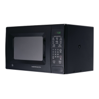
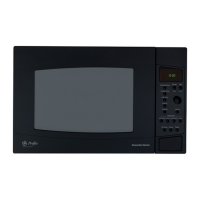
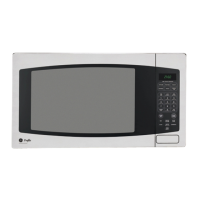
Related product manuals