LX: OPM_LPA_11U_5K0_10K_1US_V021
21
GE DE LanPro-11U UPS: Installation / User Manual 2.1 (US)
GE Digital Energy
g
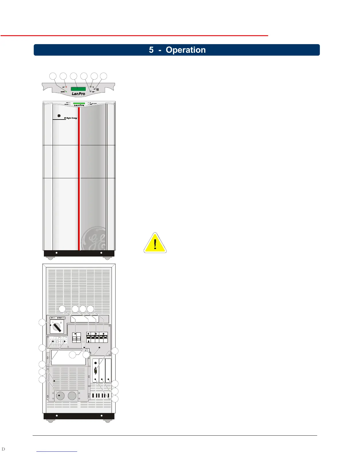
5.1 Description of Front and Rear Panel
1 LCD screen
2x16 characters, shows UPS system data, status messages, settings.
The language is selectable: English, German, French, Italian,
Spanish. Section 5.3.4 describes the selection procedure.
2-4 Push-buttons
With the button keypads ‘down’ (2) and ‘up’ (4) you can scroll through
the several screens, with keypad 'reset/enter' (3) a selection is
confirmed. Keypad activity is accompanied by a short beep. If there is
no keypad activity during 20 seconds the LCD screen will return to the
default screen (except for the service screens, see section 5.3.3).
5 LED 'operation' indicates normal operation.
6 LED ‘alarm’, indicates an alarm situation, accompanied by alarm
message(s) on the display and a sounding buzzer.
See section 5.3.2 for more information.
7 Switch ‘UPS on/off’, turns on/off the complete UPS, including the
automatic bypass!
8 Circuit breaker ‘Utility on/off’, protection fuse for utility input and
battery charger.
9 Circuit breaker ‘Bypass on/off’, fuse to protect the system in case of
severe overload or short circuit in the UPS load.
10 Manual Bypass Switch: 1 = Load on UPS
2 = Load on utility
WARNING:
In position 2, if the input line is energized, the
output is also live regardless the position of the circuit
breakers ‘utility’ and ‘bypass’.
11 Cover plate, behind it:
11a Output terminals
11b Input terminals
12 RS232/Contact Interface Card, with:
12a - RS232 Interface Port (see section 6.1)
- Emergency shutdown (see 4.4.1 and 6.2)
- Battery disconnected, pin 1-2 (can be used for external
signaling).
13 Free option slot for plug-in cards:
- Relay Card (see 6.3)
- SNMP Card (see 6.4)
14 Option slot for RPA (Redundant Parallel Architecture) Card. Not
available yet.
15 DC socket / connector.
16 Battery fuse holder
17 Conduit box
18 Cable inlet
Figure 19 :
Front and rear panel
651243
16 7 8 9
10
11a
11b
17
15
14
18
13
12
12a
11
5 - Operation