2
PRELIMINARY 10/1/03
Installation
Caution!
You must be free of all static electricity when handling elec-
tronic components. Touch a grounded, bare metal surface
before touching a circuit board or wear a grounded wrist
strap.
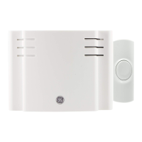
1. Insert a slotted screwdriver into the slot at the top end of
the unit and remove the cover by lifting it up (see
Figure 2).
Figure 2. Removing the Cover
2. Using the flathead mounting screws, secure the base to
the mounting surface either vertically or horizontally as
required (see Figure 3).
Figure 3. Sensor Mounting Holes
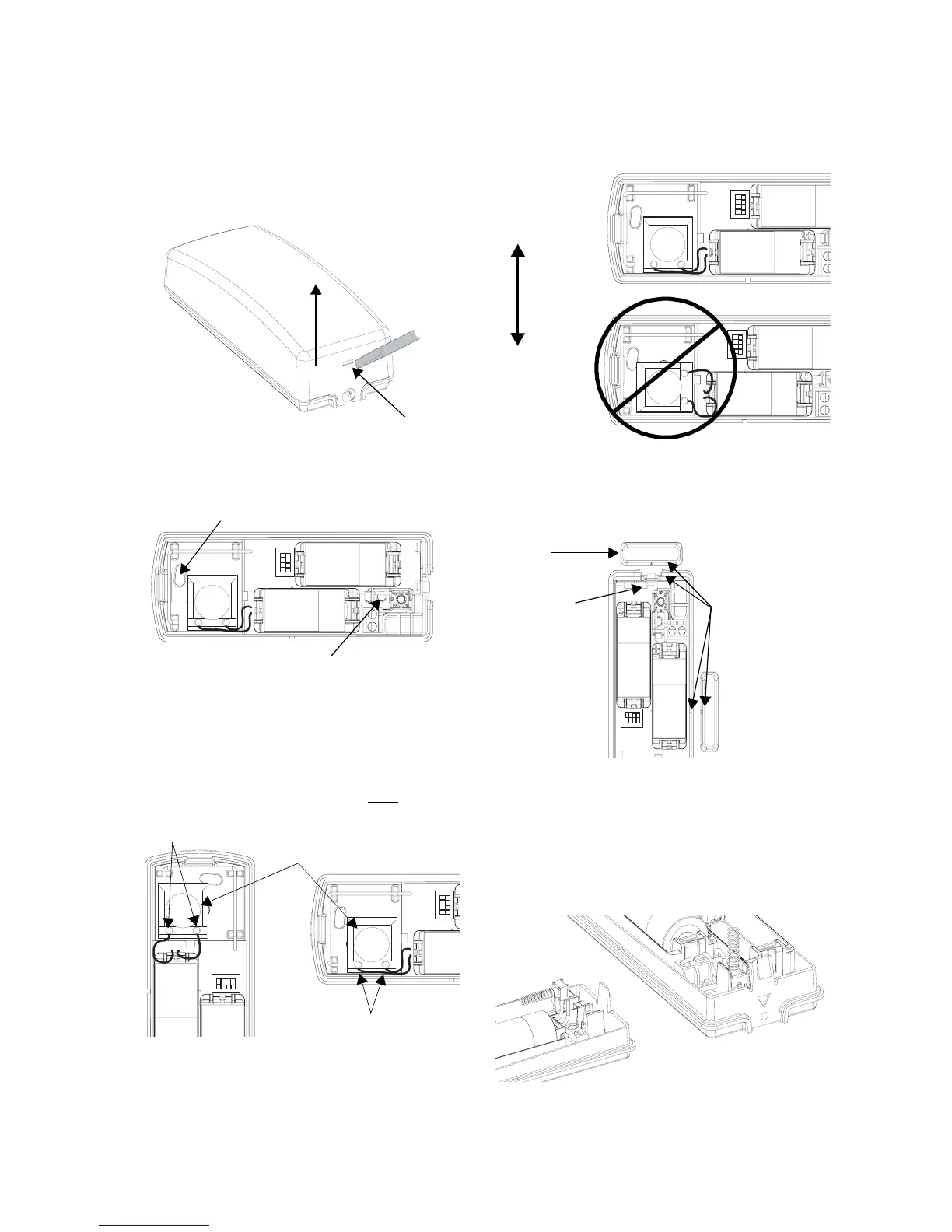
3. Position the shock element and press it firmly into its
socket.
Note
On a vertical surface, the shock sensor element must
always be oriented with its screw terminals down
, or the
writing on the shock element horizontal.
Figure 4. Positioning the Shock Element According to
Mounting Orientation on a Vertical Surface
Note
On a horizontal surface (sill or ledge), any orientation is
allowed, but certain sensor element orientations are better
than others. The element is much better at detecting hori-
zontal vibrations perpendicular to its writing than it is parallel
vibrations (see Figure 5).
Figure 5. Positioning Shock Elements for Horizontal Sur-
face Mounting
4. If using the reed switch, use the two remaining screws to
mount the magnet so its arrow is aligned with the arrow
on the sensor case (see Figure 7).
Figure 6. Possible Magnet/Reed Switch Alignment
Important!
You must disable the reed switch using the dip
switches on the circuit board if you are not using it. If
the reed switch is enabled but no magnet is installed, the
sensor will be in a continuous alarm state. See the Sensor
Settings section for more information.
5. Install the tamper switch as shown (see Figure 7).
Figure 7. Installing the Tamper Switch
6. Install the 4.7 k Ohm EOL resistor across the terminals
of the external switch block.
1 2 3 4
ON
Mounting Hole
Mounting Hole
(Wall Tamper)
1 2 3 4
ON
1 2 3 4
ON
Shock Element
Screw Terminals
Screw Terminals
1 2 3 4
ON
1 2 3 4
ON
Perpendicular
CORRECT
INCORRECT
Direction of
Vibration
1 2 3 4
ON
Magnet
Alignment
Marks
Reed Switch
1
2
 Loading...