3
PRELIMINARY 10/1/03
Setting the Detection Mode
The shock sensor has two detection modes:
• Gross Attack - detects a violent blow sufficient in length
to trip sensor.
• Pulse Count - detects a sufficient number of less violent
blows (rapping or tapping).
Pulse Count signals are counted at 1-second intervals
and stored in a 30-second digital memory. These small
signals can detect an intruder gently prying open a win-
dow or door frame.
To set the shock sensor detection modes:
1. Hold in the tamper spring. Continue to hold in while mov-
ing the DIP switches to their desired settings.
2. Set the DIP switches to the desired pulse count (see
Table 1). The LED will start blinking once a DIP switch is
moved.
3. Set the DIP Switches to the desired Gross Attack sensi-
tivity (See Table 2).
4. Release the tamper spring. The LED will flash quickly 3
times to indicate the settings have been programmed.
5. Repeat steps 1-4 each time you make a sensitivity
change. It may then be necessary to reset the DIP
switches to their proper device settings (See Sensor Set-
tings).
Testing the Detection Modes
To test the Pulse Count setting:
•
Generate small shocks on the mounting structure. Each
time a shock is detected, a pulse is registered in memory
and the LED will blink for one second. If the programmed
pulse count is reached within the most recent 30 sec-
onds, the alarm will trip and the LED will light for approx-
imately 4 seconds. If the alarm trips for any reason, the
stored pulses are cancelled.
To test the Gross Attack setting:
•
Apply high level shocks to the mounting structure, using
the LED as a guide to when the alarm trips (LED on for 4
seconds).
The LED will blink for 1 second every time the sensor
detects a pulse. A shock that is severe enough to cause
an alarm will cause the LED to light for approximately 4
seconds.
Sensor Settings
After programming the Detection Mode, the DIP switches
are used to set up the sensors use of the reed switches
and/or external contacts. If the external contact is not used
the 4.7 k Ohm EOL resistor must be installed across the ter-
minals of the external switch block.
With the tamper spring in the up position, set the DIP
switches to the desired settings (See Table 3).
Important!
DO NOT remove the reed switches from the circuit board!
The Shock Sensor will not function properly. If you don’t
need to use the reed switches, disable them with the DIP
switches as described in Table 3.
System Programming
This section describes the basic steps for adding the sensor
to panel memory. Refer to the specific panel installation
instructions for complete programming details.
The reed switch must be enabled and open when learning
the sensor.
1. With the cover on the sensor, set the panel to Program
mode.
2. Proceed to the LEARN SENSORS menu.
3. Select the appropriate sensor group and sensor number
assignments.
4. When prompted by the panel to trip the sensor, remove
the sensor cover to activate the tamper switch.
5. Exit program mode.
RF Testing
This section describes the basic steps for testing the sen-
sor. Refer to the specific panel or receiver installation
instructions for complete testing details.
1. Set the panel to Sensor Test.
2. Trip the sensor.
3. Listen for appropriate response from system sirens.
4. Exit Sensor Test.
• Use an RF Sniffer to help diagnose sensor problems.
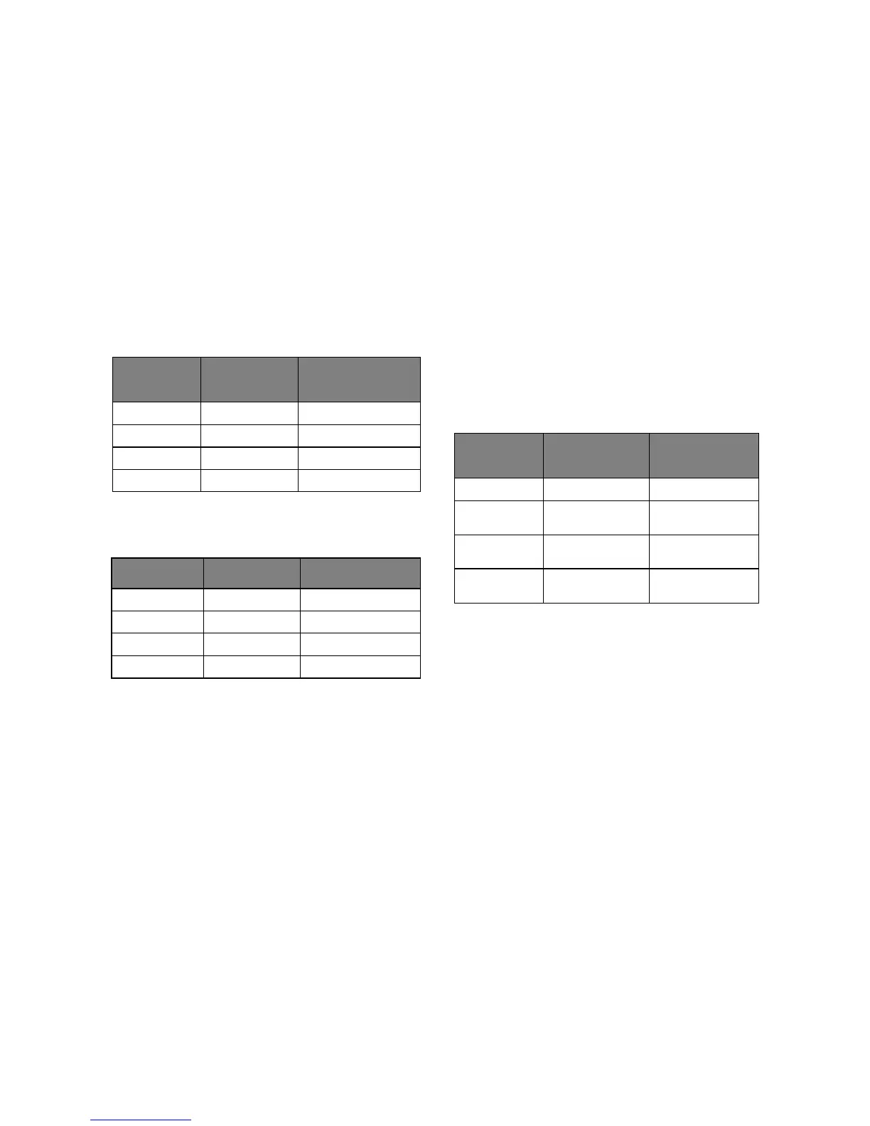
Table 1: Pulse Count Adjustment
DIP Switch 1 DIP Switch 2
30-second Pulse
Count
OFF OFF 4
ON OFF 6
OFF ON 8
ON ON Disabled
Table 2: Gross Attack Sensitivity Settings
DIP Switch 3 DIP Switch 4 Sensitivity
OFF OFF 1 (most sensitive)
ON OFF 2
OFF ON 3
ON ON 4 (least sensitive)
Table 3: Sensor Settings
Switch
Number
OFF ON
1 Unused Unused
2 Disable Reed
Switches
Enable Reed
Switches
3 Disable External
Contact
Enable External
Contact
4 External Contact
is Normally Open
External Contact is
Normally Closed
 Loading...