Do you have a question about the GE LOGIQ 200 and is the answer not in the manual?
Formal introduction to the manual's purpose and scope, outlining its objectives and organization.
Details the primary goals of the QA program and the reference manual.
Provides essential instructions for cleaning ultrasound probes safely and effectively.
Section for recording customer and site specific information for the QA test.
Lists and describes the test equipment used for performing the QA checks.
Procedures for verifying electrical safety of the system and its environment.
Guidelines for inspecting and cleaning the ultrasound system components.
Procedures for verifying the operation of system controls and various imaging modes.
Detailed tests to assess the performance and consistency of probes.
Procedures for running system diagnostics and interpreting test results.
Lists the necessary equipment for performing leakage current testing procedures.
Specifies the acceptable leakage current values according to GEMS standards.
Details the method for measuring and verifying the system's grounding continuity.
Test procedure for measuring chassis leakage current under various conditions.
Method for testing transducer leakage current without probe adapters.
Final safety tests for probes to be performed after system rework.
Comprehensive procedures for evaluating ultrasound probe performance using a phantom.
Final steps for completing and documenting the QA procedure, including customer sign-off.
| Category | Ultrasound System |
|---|---|
| Manufacturer | GE Healthcare |
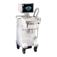
| Model | LOGIQ 200 |
| Power Requirements | 100-240 VAC, 50/60 Hz |
| Application | General Imaging |
| Display | CRT |
| Transducer Ports | 2 |
| Scan Modes | B-mode, M-mode |