EasyManua.ls Logo

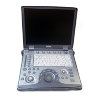
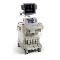
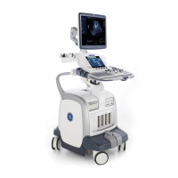
GE LOGIQ S8

GE LOGIQ S8
418 pages
To Next Page IconTo Next Page
Loading...
GE Healthcare
(FEBRUARY
28
,
2019)
COVER.FM
PRELIMINARY
LOGIQ S8/LOGIQ E8
Service Manual
Document Number: 5394227
Revision: 12

Table of Contents

Other manuals for GE LOGIQ S8

Questions and Answers:

GE LOGIQ S8 Specifications

General IconGeneral
TypeUltrasound System
Display TypeLCD
3D/4D ImagingYes
ConnectivityDICOM, USB, Ethernet
Display Size19 inches
TransducersLinear, Convex, Phased Array
Doppler ModesColor Doppler, Power Doppler, Spectral Doppler
Operating ModesB-Mode, M-Mode
ApplicationsAbdominal, Cardiac, Obstetrics, Gynecology, Vascular, Musculoskeletal
PortabilityCart-based
Transducer Ports4

Summary

Important Precautions

Translation Policy

Details the policy regarding the manual's availability and the user's responsibility for translation services.

Chapter 1 Introduction

Section 1-1 Overview

Provides an overview of the chapter's purpose and contents.

Section 1-2 Service Manual Overview

Describes the structure and contents of the service manual.

Models Covered by this Manual

Lists the specific models and configurations covered by the manual.

Product Description

Provides a general overview of the LOGIQ S8/E8 ultrasound system's capabilities.

Important Conventions

Explains the icons, labels, and conventions used in the manual.

Standard Hazard Icons

Explains various graphical icons used to denote hazards.

Product Icons

Describes the purpose and location of safety labels and other information provided on the equipment.

Section 1-4 Safety Considerations

Covers critical safety precautions for operating and servicing the system.

Mechanical Safety

Details precautions related to the mechanical aspects of the system.

Electrical Safety

Provides safety guidelines for electrical connections and handling.

Auxiliary Devices Safety

Outlines safety considerations when using auxiliary devices and peripherals.

Battery Safety

Provides safety instructions for the system's lithium-ion battery.

Section 1-5 Labels Locations

Details the location and purpose of various labels and icons on the system and its components.

Section 1-6 Dangerous Procedure Warnings

Highlights warnings that precede potentially dangerous procedures.

Section 1-7 LockoutTagout (LOTO) Requirements

Outlines the requirements for applying Lockout/Tagout procedures for safety.

Section 1-8 ReturningShipping System, Probes and Repair Parts

Provides guidelines for returning or shipping system components and repair parts.

Section 1-9 Electromagnetic Compatibility (EMC) and Electrostatic Discharge (ESD)

Covers EMC and ESD precautions critical for system performance and safety.

Section 1-10 Customer Assistance

Lists contact details for GE Healthcare support and information.

Chapter 2 Site Preparations

Section 2-1 Overview

Provides information for planning and preparing the site for LOGIQ S8 setup.

Section 2-2 General Console Requirements

Details essential requirements for the system's console, including environmental factors.

Electrical Requirements

Outlines the necessary electrical specifications and considerations for system installation.

EMI Limitations

Discusses susceptibility to and generation of Electromagnetic Interference (EMI).

Probe Environmental Requirements

Specifies environmental parameters for probes during operation, storage, and transport.

Section 2-3 Facility Needs

Outlines the responsibilities of the purchaser in preparing the installation site.

Required Facility Needs

Details mandatory site requirements including power, space, and network connections.

Desirable Features

Lists optional site recommendations for optimal setup.

Minimal Floor Plan Suggestions

Provides a visual layout suggestion for the system installation area.

Networking Setup Requirements

Outlines requirements for connecting the system to a network.

Section 2-4 Environmental Dangers

Covers safety aspects related to the patient environment and potential environmental hazards.

Patient Vicinity UL60601-1 (USA)

Defines the patient vicinity safety zone according to UL60601-1 standards.

Patient Environment IEC60601-1 (IEC60601-1-1) and ANSI AAMI ES60601-1

Defines the patient environment based on IEC and ANSI standards.

Chapter 3 System Setup

Section 3-1 Overview

Provides information for setting up the LOGIQ S8 system.

Section 3-2 Setup Reminders

Offers practical tips and reminders for a smooth system setup process.

Setup Warnings

Lists critical warnings and safety precautions to observe during system setup.

Section 3-3 Receiving and Unpacking the Equipment

Details procedures and warnings for receiving and unpacking the system.

Damage in Transportation

Provides procedures to follow if damage is apparent during transportation.

The Tilt & Shock Indicators (if applied)

Explains the purpose and location of tilt and shock indicators.

Transportation Box Label

Illustrates and explains the labels found on the transportation box.

Unpacking the LOGIQ S8

Describes the recommended procedure for unpacking the LOGIQ S8 unit.

Packing Materials - Recycling Information

Provides information on the recyclability of packing materials.

Section 3-5 Preparing for Setup

Covers essential pre-installation steps including order verification and physical inspection.

Section 3-6 Completing the Set Up

Details system specifications and guides the final steps of installation.

Electrical Specifications

Details electrical specifications and voltage verification for the LOGIQ S8.

Connection the IO Rear Panel

Explains how to connect external I/O devices to the rear panel.

Connecting Probes

Provides instructions and precautions for connecting ultrasound probes.

Connecting the CW Pencil Probe (LOGIQ S8 LOGIQ S8 Vet)

Details the procedure for connecting the CW Pencil Probe.

Connecting the TEE Probe

Explains how to connect the TEE probe using the RS-DLP adapter.

Section 3-7 Power OnOff

Covers the procedures for powering the system on and off, including safety precautions.

Connect AC (mains) Power to the LOGIQ S8

Details the process of connecting AC power to the system, including preliminary checks.

Power ON

Describes the steps for powering on the system and what to expect during the boot process.

Login

Explains the login process and user acknowledgment of regulations.

LogoffShutdownExit

Outlines options for logging off, shutting down, or exiting the system.

Complete Shutdown

Details the steps for performing a complete system shutdown.

Sleep Mode (R1 to R4)

Explains how to put the system into Sleep Mode.

To Change Your Password

Guides on how to change the user password.

Password Policies

Describes how to create and set password policies for system access.

Disk Encryption

Explains how to enable and manage disk encryption for data security.

Section 3-8 System Configuration

Describes how to configure the LOGIQ S8 system, including initial setup steps.

Enter Location, Adjust DateTime, Select Language

Guides on configuring system location, date, time, and language settings.

Software Option Installation

Details the process of installing software options using a password or key code.

Section 3-9 Optional PeripheralsPeripheral Connection

Provides guidance on connecting optional peripherals and accessories to the system.

Connecting the Secondary Patient LCD Monitor

Details how to connect the secondary patient monitor, including safety precautions.

Connecting the Off-BoardOn-Board UVC

Details the connection procedure for the off-board UVC.

Connecting the On-Board UVC

Details the connection procedure for the on-board UVC.

UVC Functional Check Procedure

Outlines the steps to perform a functional check of the UVC.

Connecting the Footswitch

Explains how to connect the footswitch and configure its parameters.

ECG Connector

Shows the location of the ECG connector on different system versions.

Connecting the USB Flash Drive and USB External Hard disk drive

Provides instructions for connecting USB storage devices, including precautions.

Section 3-10 Printer Installation

Details the procedures for installing and configuring printers for the system.

Installing Digital Black & White Printer Sony UP-D897 D898

Details the installation process for Sony UP-D897/D898 printers.

UP-D897 D898 - Printer Settings

Provides recommended settings for the UP-D897/D898 printer.

Installing Digital Color Printer Sony UP-D25 MD

Details the installation process for the Sony UP-D25MD color printer.

Adding the Printer to the System

Explains how to add a printer to the system's configuration.

Setting the Printer to Print Reports

Guides on configuring the printer to output reports.

PC Printer Setup

Details the steps for setting up a PC printer with the system.

Section 3-11 Connectivity Setup

Provides guidance on establishing system connectivity options.

Connectivity Introduction

Introduces connectivity options between the system and other devices.

The Dataflow Concept

Explains the Dataflow concept for customizing the system's data transfer.

Stand-alone LOGIQ S8

Describes the setup for a stand-alone LOGIQ S8 scanner without network connection.

LOGIQ S8 + PC within a Sneaker Net

Explains how to set up LOGIQ S8 with PCs via sneaker net.

Connection between LOGIQ S8 and DICOM Server

Details how to connect the system to a DICOM server in a network environment.

Wired Ethernet from LOGIQ S8 to a Workstation

Explains wired Ethernet connection methods to a workstation.

Connection using Wireless Option (R2.x.x or later)

Describes how to establish a connection using the wireless option.

Network Icon

Explains the meaning of network icons displayed on the system.

Section 3-12 Configuring Connectivity

Provides guidance on establishing system connectivity options.

Connectivity Functions

Lists and describes various connectivity functions available on the system.

TCPIP

Details how to configure TCP/IP settings for system and network connectivity.

Device

Explains how to add, manage, and ping connected devices.

Service

Details how to add and configure services for destination devices.

Instructions for Setting up Network Storage on LOGIQ S8 R4

Provides step-by-step instructions for configuring network storage.

Section 3-13 Setting up InSite Connection (R1 to R4)

Guides on setting up the system to connect to an InSite server for remote service.

Prerequisites for InSite Setup

Lists the information required from the IT administrator for InSite setup.

Configuration Steps

Details the steps for configuring the system for InSite connection.

Configuring InSite

Guides on configuring the system to connect to the InSite server.

Configuring Agent Configuration

Explains how to configure the agent settings for InSite connection.

Configuring Advanced Configuration

Details how to configure advanced settings for the InSite connection.

Configuring Request for Service (RFS)

Explains how to configure the system to submit Request For Service (RFS).

Verifying InSite Connection - CSD

Guides on verifying the InSite connection using the Common Service Desktop.

Verifying InSite Connection - VCO

Explains how to verify InSite connection using Virtual Console Observation.

Section 3-15 Connectivity Setup Worksheet

Provides a worksheet to document connectivity setup details.

Section 3-16 Paperwork

Lists all product manuals and documentation related to the LOGIQ S8 system.

Product Locator Installation Card

Shows an example of the Product Locator Installation Card.

User Manual(s)

Advises to check for correct User Manuals and their language versions.

Chapter 4 Functional Checks

Section 4-1 Overview

Introduces the functional checks for the LOGIQ S8 and their purpose.

Section 4-3 General Procedures

Covers general procedures including system cover requirements and power lockout.

Power ON

Details the procedure for powering on the system.

Login

Explains the login procedure and user acknowledgment.

LogoffShutdownExit

Outlines options for logging off, shutting down, or exiting the system.

Complete Shutdown

Details the steps for performing a complete system shutdown.

Monitor Positions Adjustment

Describes the operating range for adjusting the monitor position.

Monitor Arm Lock

Explains how to lock the monitor arm for stability.

Operator Panel Position Adjustment

Details how to adjust the vertical position of the operator panel.

To Move the Operator Panel from Side to Side

Explains how to adjust the horizontal position (swivel) of the operator panel.

Caster

Describes how to lock and unlock the swivel/brake casters.

Total Lock Caster

Explains how to engage the total lock on casters.

Moving and Transporting the LOGIQ S8

Provides comprehensive guidelines and precautions for safely moving and transporting the LOGIQ S8 system.

Moving the System

Details the procedure for physically moving the system, including safety checks.

Transporting the System

Provides guidelines for safely transporting the system using vehicles.

Setting up at a New Location

Covers procedures for setting up the system after moving it to a new location.

Service Platform Confirmation (R1 to R4)

Verifies the version and status of the service platform on R1 to R4 systems.

Section 4-4 Functional Checks

Describes functional checks to verify system operation and aid in troubleshooting.

Overview

Introduces the functional checks for the LOGIQ S8 and their purpose.

Preparation

Outlines initial steps required before performing functional checks.

Basic Controls

Provides a labeled diagram of the system's control panel.

Trackball Area

Explains the functions and usage of the trackball and its associated controls.

Performance Tests

Suggests optional test phantoms for QA and system testing.

B-Mode Checks

Details the steps and controls used to optimize and verify B-Mode image quality.

M-Mode Checks

Outlines preparations for M-Mode checks, including phantom use and scanner setup.

Color Flow Mode Checks

Outlines preparations for Color Flow checks, including phantom use and scanner setup.

PWCW Doppler Mode Checks

Outlines preparations for PW/CW Doppler checks, including probe connection and scanner setup.

Tissue Velocity Imaging (TVI) Checks

Outlines preparations for TVI checks, including probe connection and scanner setup.

Adjust the TVI Controls

Details how to adjust TVI controls to optimize image quality and reduce noise.

SWE (Shear Wave Shear Elasto) Functional Check

Details steps to perform a functional check of the SWE option.

Cineloop Check

Explains what a cineloop is and how it's used.

Basic Measurements

Guides on performing distance, tissue depth, and circumference/area measurements.

System Integration Checks

Verifies the integration of system components, including the operator panel.

Operator Panel Test

Details how to test the operator panel's controls and display functions.

DVD Drive Test

Guides on testing the DVD drive's read/write capabilities.

LAN Port Test

Outlines how to test the LAN port for network recognition.

ProbeConnectors Checks

Provides instructions for safely connecting probes, including handling precautions.

To Connect a Probe

Provides instructions for safely connecting probes, including handling precautions.

TEE RS-DLP adapter + TEE probe

Details connecting TEE probes with the RS-DLP adapter.

ECG Check

Explains ECG capability and how to perform checks using cables or a simulator.

Peripheral Checks

Checks the functionality of various peripherals like DVR, printers, and media drives.

Hardware DVR Test (if equipped on R1.x.x or R2.x.x)

Guides on testing the hardware DVR functionality.

Software DVR Test (if equipped on R3.0.0 and later)

Guides on testing the software DVR functionality.

Black and White Printer Test

Outlines steps to test the black and white printer functionality.

Color Printer Test

Outlines steps to test the color printer functionality.

CDDVD ReadWrite Test

Details how to test the CD/DVD drive's read/write capabilities.

Gel Warmer Test

Describes how to test the gel warmer functionality.

Single CWD

Guides on testing the Continuous Wave Doppler (CW) function.

System Exterior Visual Check

Guides on performing a visual inspection of the system's exterior components.

Physical Abnormalities

Instructs to check the system exterior for loose or cracked parts.

Label Check

Details how to check for the presence and condition of system labels on R1-R3 models.

Appearance Inspection

Guides on checking the system's appearance and product labels.

Mechanical Functions Checks

Verifies the mechanical operations of the system, including monitor and casters.

Extended Battery (Option)

Outlines the procedure for testing the Extended Battery option.

3 D4 D (Option)

Details how to test the 3D/4D option, including probe preparation.

Volume Navigation (Option)

Refers to a specific section for Volume Navigation functional checks.

FibroScan Module (Option)

Describes tests for the FibroScan module, including LED checks and probe interaction.

Section 4-5 Application Turnover Check List

Lists checks for date, time, location, language, and printer key assignments.

Software Configuration Checks

Lists checks for date, time, location, language, and printer key assignments.

Section 4-6 Power Supply Test and Adjustments

Covers testing and adjusting the system's power supply.

Power Supply Test Procedure

Instructs to run the System Voltage test.

Power Supply Adjustment

States that power supplies are self-regulated and have no adjustments.

Section 4-7 Site Log

Provides a template for recording site maintenance and service information.

Chapter 5 Components and Functions (Theory)

Section 5-1 Overview

Explains system concepts, component arrangement, and subsystem functions.

General Information

Provides general information about the LOGIQ S8 system and its operating modes.

System Exterior

Illustrates and labels the exterior components of the R1, R2, and R3 system models.

Operator Panel

Illustrates and labels the operator panel controls for R1-R3 and R4 and later models.

Probe Connector

Shows the location of probe ports on the system.

System Options

Illustrates various system options and their locations on the chassis.

USB Ports

Shows the location and types of USB ports on the system and OPIO.

Rear Panel

Illustrates and describes the connectors on the rear panel of the system.

Section 5-3 Power Distribution

Explains the sequence of events during system power-up.

Section 5-4 Power Loss Description

Describes the effects of a power loss on the system and its components.

Section 5-5 Software Overview

Describes the software versions used on the LOGIQ S8 based on Windows Embedded.

Section 5-6 Software Options

Lists and describes available software options for different system revisions.

Section 5-7 Hardware Options.

Lists available hardware options and their compatibility across different software revisions.

Section 5-8 Regional and Peripheral Options

Lists optional peripherals, including printers, that can be connected to the system.

Section 5-9 Air Flow Distribution

Explains the air flow path through the system for cooling.

Section 5-10 Product Manuals

Lists all product manuals and documentation related to the LOGIQ S8 system.

Section 5-11 LOGIQ E8

Highlights the key differences between the LOGIQ S8 and LOGIQ E8 systems.

Chapter 6 Service Adjustments

Section 6-1 Overview

Describes how to test and adjust mechanical system capabilities that may be out of specification.

Section 6-2 Monitor Adjustment

Details how to adjust the settings of the 19" LCD monitor using the digital control panel.

22 (OLED) and 23 Wide Monitor Adjustment

Guides on adjusting settings for 22" OLED and 23" wide monitors.

Section 6-3 Volume Navigation Calibration Procedure

Explains the Volume Navigation system calibration and its purpose.

Setup

Details the setup process for Volume Navigation calibration, including phantom placement and magnetic distortion testing.

Measure Initial Accuracy

Guides on measuring initial accuracy to evaluate calibration effectiveness.

Perform Calibration

Provides detailed steps for performing the Volume Navigation calibration procedure.

Chapter 7 DiagnosticsTroubleshooting

Section 7-1 Overview

Describes tools and software for maintaining image quality and system operation, including diagnostics.

Section 7-2 Service Platform

Explains different access and security levels within the Service Platform.

Remote Access to Service Platform

Explains remote access technology for diagnostics and troubleshooting.

Customer Granting Full Remote Access Permission to GE Service Technician

Describes how customers grant remote access permission to GE service technicians.

Section 7-3 Gathering Troubleshooting Data (R1 to R4)

Explains how to acquire problem images and system data for service analysis.

Collecting Vital System Information

Details the necessary information to collect for analyzing malfunctions or returned systems.

Request for Service (RFS)

Explains how to configure the system to submit Request For Service (RFS).

Collecting a Screen Capture with Logs

Details how to capture screen images and collect system logs for troubleshooting.

Capturing Network Logs with Network Sniffer

Provides instructions on capturing and analyzing network logs using specialized tools.

Section 7-4 Service Desktop (CSD) - R1 to R4

Describes the features and functions of the Common Service Desktop (CSD).

Error Logs

Explains how to view and interpret system error logs using the Log Viewer.

Diagnostics

Details how to perform common service components and diagnostics tests.

Image Quality

Explains how to verify image quality within the system.

Configuration

Provides information on viewing and modifying device information and configurations.

Utilities - Common Utilities

Describes various common utilities for system management and troubleshooting.

Section 7-6 Service Desktop (R4.2.5 x and later)

Describes the features and access levels of the Service Desktop for R4.2.5x systems.

Disruptive Mode

Explains how to control interruptions to operation using Disruptive Mode.

Licenses

Lists available options with Service Basic Access, including HOME and Utilities.

Home

Explains how home configurations vary depending on the purchased service level.

System Information

Displays general information about the LOGIQ S8 system configuration.

Software Status

Provides information about the installed software versions and application status.

Connected Probes

Shows information about probes connected to the LOGIQ S8, including status and serial numbers.

Utilities

Lists various utility configurations and related information.

Change Password

Allows changing the password for specified user types, with data loss warnings.

Data Transfer

Provides methods for viewing and setting up automatic or manual data file transfers.

Delete Files

Explains how to delete files and folders from the D:\Service directory.

Gather Logs Utility

Provides a way to collect system logs and place them in the D:\Service directory.

Network Capture

Displays network traffic and provides tools to capture network logs for analysis.

SSA License

Provides functionality to view SSA key details, status, and restore licenses.

Third Party Software Licenses

Displays third-party software licenses used as part of the service platform.

Options

Allows viewing and managing software options and their details.

Agent Configuration

Explains how to edit and configure agent settings for remote service.

Section 7-7 Troubleshooting Trees, Instructions and Tech Tips

Provides guidance on troubleshooting common system issues and shortcut keys.

System does not boot up

Offers a flowchart for troubleshooting system boot-up issues.

Noise disturbs the Image

Provides steps for troubleshooting image noise issues.

Trackball - Impaired sensitivity

Offers a flowchart for troubleshooting trackball sensitivity issues.

Printer Malfunction

Provides a flowchart for troubleshooting printer malfunctions.

19 Monitor Troubleshooting

Guides on troubleshooting issues with the 19-inch monitor.

Universal Video Converter Troubleshooting

Provides troubleshooting steps for the Universal Video Converter.

4 D Option Trouble shooting

Offers troubleshooting steps for issues related to the 4D option.

Power Assistant Option Trouble Shooting

Provides troubleshooting steps for issues related to the Power Assistant option.

Extended Battery Option Trouble Shooting

Details troubleshooting steps for issues with the Extended Battery option.

Privacy and Security Trouble Shooting

Addresses troubleshooting for password policies, disk encryption, and virus protection.

Slow Response Rate between the LOGIQ S8 and a DICOM (PACS) Server

Provides steps to troubleshoot slow response rates in DICOM server connections.

Electromagnetic Interference (EMI) Troubleshooting

Offers methods for troubleshooting EMI issues, including prevention and abatement.

Connectivity Troubleshooting

Provides solutions for common connectivity issues with the system.

User Group Management and User Right Control (For R4)

Addresses issues related to user group management and right control in R4 systems.

Chapter 8 Renewal Parts

Section 8-1 Overview

Provides an overview of renewal parts and accessories for the system.

Optional Peripherals and Accessories

Lists and describes optional peripherals, including printers, available for the system.

Probes

Details various probes available for the system, including part numbers and applications.

Power Cord

Lists various power cords and their part numbers for different regions and voltage requirements.

Chapter 9 Care & Maintenance

Section 9-1 Overview

Introduces the chapter on care and maintenance for the scanner and peripherals.

Warnings

Provides essential safety warnings for system maintenance.

Why Do Maintenance

Explains the importance of maintaining records and quality assurance programs.

Maintenance Task Schedule

Specifies the recommended frequency for servicing and items requiring attention.

Tools Required

Lists special tools, supplies, and equipment needed for periodic maintenance.

System Maintenance

Covers preliminary checks and system functional checks for maintenance.

Functional Checks

Details system functional checks for B-Mode, Color Flow, Doppler, and other modes.

PeripheralOption Checks

Checks the functionality of peripherals and optional hardware.

Mains Cable Inspection

Provides steps for inspecting the mains cable and its connectors.

Optional diagnostic checks

Suggests viewing error logs and running diagnostics for system checks.

Cleaning

Provides guidelines for general cleaning and appropriate disinfectant agents.

Air Filter Cleaning

Details the procedure for cleaning the system's air filters to prevent overheating.

Physical Inspection

Instructs to check the system exterior for loose or cracked parts and labels.

Probe maintenance

Provides guidance on probe care, handling, and cleaning to prevent damage.

Electrical Safety Tests

Outlines electrical safety tests based on industry standards for medical equipment.

GEHC Leakage Current Limits

Specifies leakage current limits for system operation based on voltage configurations.

Outlet Test - Wiring Arrangement - USA & Canada

Details how to test electrical outlets for proper grounding and wiring arrangement.

Grounding Continuity

Explains how to measure ground wire resistance for electrical safety.

Chassis Leakage Current Test

Measures current flow from the chassis to ground under normal and fault conditions.

Isolated Patient Lead (Source) Leakage-Lead to Ground

Measures current flow from isolated ECG leads to ground, simulating patient contact.

Isolated Patient Lead (Source) Leakage-Lead to Lead

Tests leakage current between ECG lead combinations.

Isolated Patient Lead (Sink) Leakage-Isolation Test

Measures leakage current from isolated patient leads to ground.

Probe Leakage Current Test

Measures current flow from probes to ground through a patient during scanning.

Mains on Applied Part

Tests sink leakage current by applying mains voltage to the probe's insulation barrier.

e-TRAX (source) Leakage Current Test

Measures current flow from e-TRAX Needle sensor to ground through a patient.

e-TRAX Leakage current - Mains to CF Applied part

Measures leakage current flow from mains to the CF Applied part.

When Theres Too Much Leakage Current...

Provides troubleshooting steps for issues related to excessive leakage current.

Chassis Fails

Troubleshooting steps for chassis failures related to grounding and connections.

Probe Fails

Guides on isolating probe failures by testing with different probes.

Peripheral Fails

Troubleshooting steps for peripheral failures, focusing on grounds and connections.

Still Fails

Provides isolation steps by removing peripherals to monitor leakage current.

ECG Fails

Instructs to inspect ECG cables for damage or poor connections.
Ultrasound Equipment Quality Check (EQC and IQC)

Advises to download and use the latest versions of EQC and IQC forms.

Related product manuals