GE HEALTHCARE
DIRECTION 5394227, 12 LOGIQ S8/LOGIQ E8 SERVICE MANUAL
Section 5-3 - Power Distribution 5 - 11
Section 5-3
Power Distribution
5-3-1 Purpose of this section
The power distribution within the LOGIQ S8 is described in this section.
5-3-2 Power Up Sequence Description
The Power Up Sequence can be divided in the following steps:
1.) Connect the mains power to the LOGIQ S8 and switch Circuit Breaker to ON position.
2.) Press the Power ON button on the Operator Panel.
3.) BEP (and system) power-up.
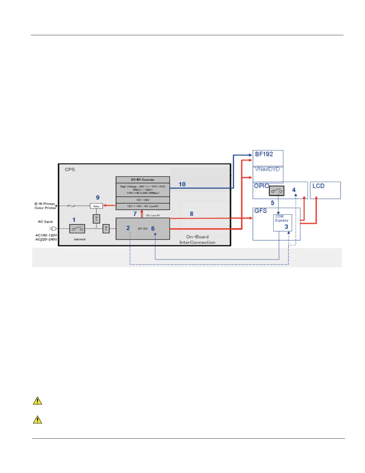
Sequence
1.) Circuit breaker ON
2.) AC/DC Unit creates Stand-by Power
3.) Stby Power routed to COM Express
4.) Stby Power routed to OPIO (LED)
5.) Main ON signal from OPIO
6.) COM Express Sends ON Signal to AC/DC
7.) AC/DC route 12V to DC-DC Controller
8.) AC/DC route 12V to system
- GFS, BF192, and VNav/DVD/FibroScan module
- GFS powers OPIO and LCD
9.) Main AC power routed to Peripherals (Printers)
10.)DC-DC sends HV to BF192
NOTICE
For LOGIQ S8/LOGIQ E8 system, Power-ON using Battery is NOT allowed.
NOTICE
From R4 system, AC/DC automatically turns on to charge battery on Stand-by state (Sequence 2
above).