Modifications reserved Page 10/66
OPM_LPS_3UO_80K_M10_1US_V010.doc User Manual LP33 Series 80 & 100 UL S1
Q
2
I
O
N
0 OFF
F
1
1
-
1
2
-
1
3
Q
1
I
O
N
0 OFF
SNMP
CI
RS232
RC
Q2 Q1
FTM3
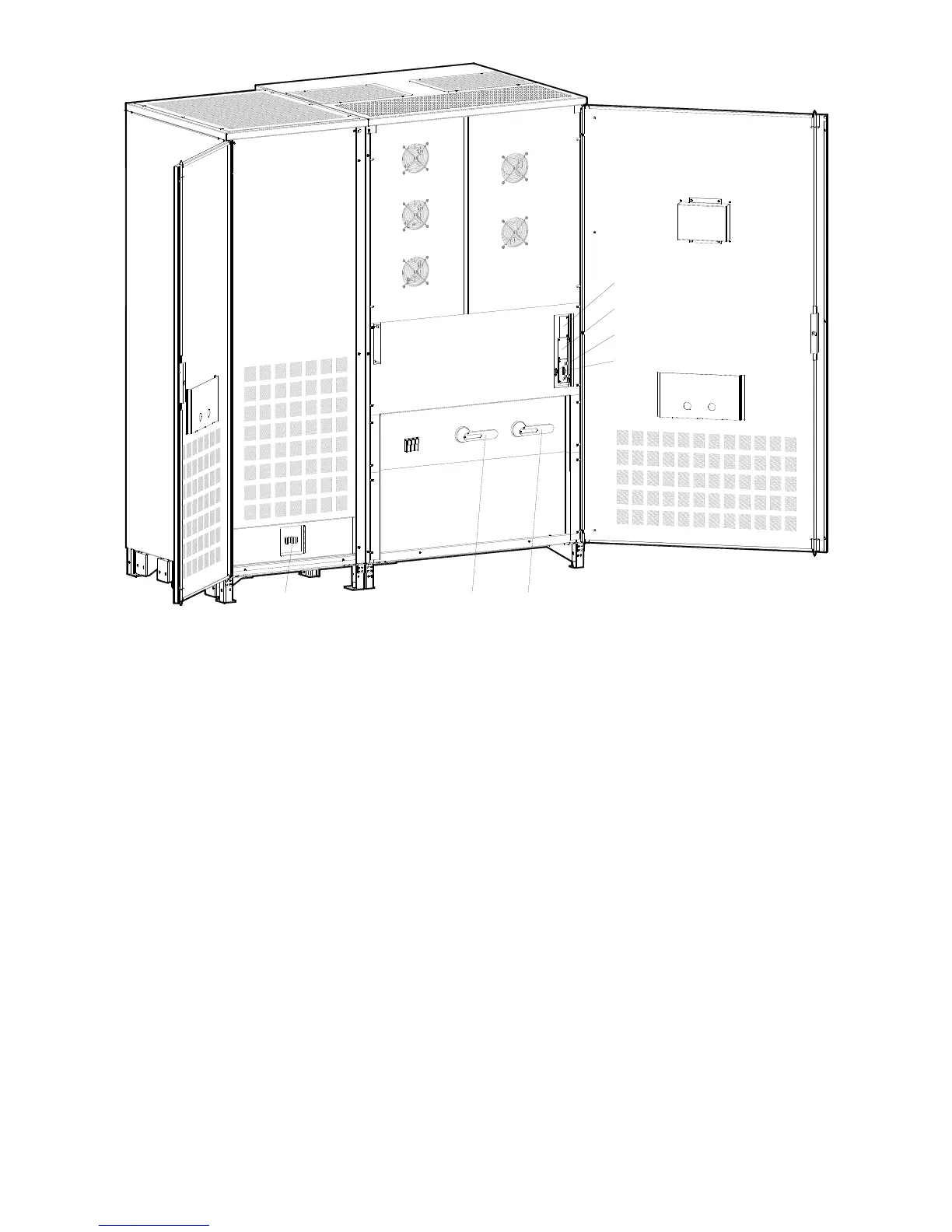
Fig. 2.1-7 General view with open door – UPS with Battery Cabinet 26”/650mm
BC Battery cabinet
(option)
CI Customer Interface Board (option)
F11-12-13 Power Supply Fuses (6-1/4A 600Vac Class CC)
Attention: only for Service purposes.
Don’t open during UPS operation!
FTM3 Battery Breaker
(option)
Q1 UPS output switch
Q2 Manual bypass switch
RC Relay card
RS232 Serial port RS232
SNMP 3-ph SNMP/WEB plug-in
adapter (option)

 Loading...