Modifications reserved Page 25/66
OPM_LPS_3UO_80K_M10_1US_V010.doc User Manual LP33 Series 80 & 100 UL S1
LP33 Series S1 100KVA
UPS Model UPS series number UPS nominal rating (kVA)
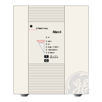
Battery level LED
All LED light indicate a battery autonomy of 100%.
LED A Fixed: indicates battery autonomy between 6% and 25%.
Blinking: indicates battery autonomy ≤5%.
LED A, B Indicate battery autonomy between 26% and 50%.
LED A, B, C Indicate battery autonomy between 51% and 99%.
Min: Battery autonomy time in minutes estimates with actual load.
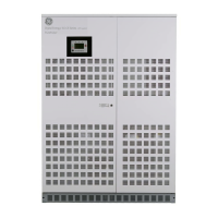
Load level LED
All LED OFF indicate a load status at ≤25%.
LED A Indicates a load level between 26% and 50%.
LED A, B Indicate a load level between 51% and 75%.
LED A, B, C Indicate a load level between 76% and 100%.
LED A, B, C, D Indicate a load level between 101% and 124%.
LED D blinking Indicates a load level ≥125%.
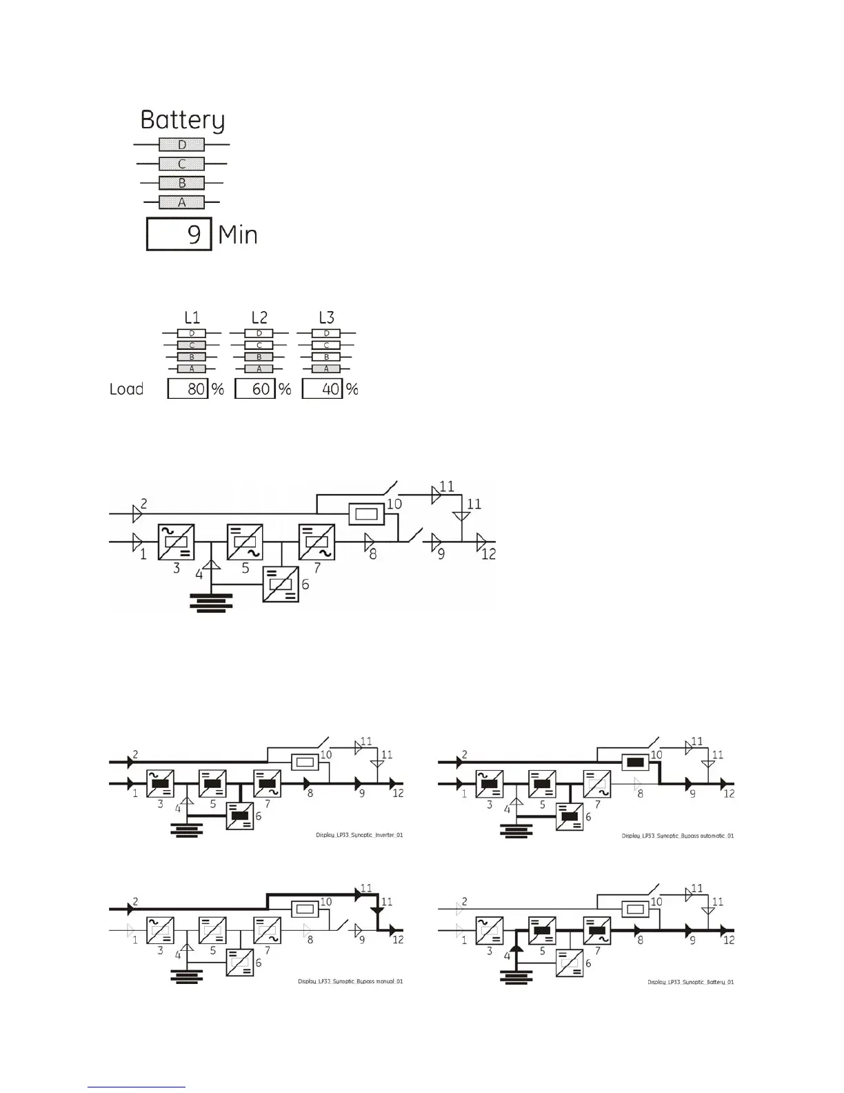
Fig. 6.1-2 LEDs on synoptic diagram
LEDs on synoptic diagram
LED 1 Utility rectifier OK
LED 2 Utility bypass OK
LED 3 Rectifier ON
LED 4 Discharging battery
LED 5 Booster ON
LED 6 Charge battery ON
LED 7 Inverter available
LED 8 Inverter ON
LED 9 Q1 closed
LED 10 Automatic bypass ON
LED 11 Manual bypass Q2 ON
LED 12 Load on UPS
Examples of typical scenarios in the synoptic diagram:
Load supplied by Inverter Load supplied by Automatic Bypass

 Loading...