IMPORTANT SAFETY NOTICE: This information is intended for use by individuals
possessing adequate background of electrical, electronic and mechanical experience.
Any attempt to repair a major appliance may result in personal injury and property
damage. The manufacturer or seller cannot be responsible for the interpretation of this
information, nor can it assume any liability in connection with its use.
DISCONNECT POWER BEFORE SERVICING.
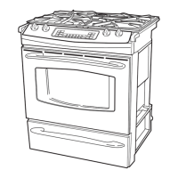
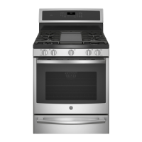
MODEL NUMBER
PGS908
IMPORTANT SERVICE INFORMATION
DO NOT DISCARD
30" SLIDE-IN NON-CONVECTION
GAS SELF-CLEAN RANGE
Gas Inlet
Shut-Off Lever
Shown in the
Open Position
Gas Supply
to Oven
Gas Supply to
Top Burner
Pressure Regulator
as see from Front of
Range
OVEN GAS SHUT-OFF VALVE
The gas shut-off valve is located on the side of the
pressure regulator which is mounted to the back of
the range. Access to the shut-off lever is obtained
by removing the storage drawer and reaching
through the opening on the right side of the control box.
NOTE: The oven shut-off valve shuts off the gas to
the oven only and has no effect on the top burners.
Removal position
3. Firmly grasp both sides of the door at the top.
4. Close door to the door removal position, which
is halfway between the broil stop position and
fully closed.
5. Lift door up until the hinge arm is clear of the slot.
REMOVABLE OVEN DOOR
The door is very heavy. Be careful when removing and lifting the door.
Do not lift the door by the handle.
TO REMOVE:
1. Fully open the door.
2. Push the hinge locks down toward the door frame, to the unlocked
position. A tool, such as a small flat-blade screwdriver, may be required.
Slot
Hinge
Lock
Pull hinge locks
down to unlock
Pressure Regulator as Seen
from Front of Range
TO REPLACE:
1. Firmly grasp both sides of the door at the top.
2. With the door at the same angle as the removal
position, seat the indentation of the hinge arm into the
bottom edge of the hinge slot. The notch in the hinge
arm must be fully seated into the bottom of the slot.
Push hinge locks up to lock
3. Fully open the door. If the door will not fully open, the
indentation is not seated correctly in the bottom edge
of the slot.
4. Push the hinge locks up against the front frame of the
oven cavity, to the locked position.
5. Close the oven door.
Bottom Edge
of Slot
Hinge Arm
Indentation
Hinge Arm
Hinge Lock
MAINTOP REMOVAL AND ACCESS TO SPARK MODULE
1. Cut off gas supply to range.
2. Cut off electrical supply to range.
3. Remove the control panel as follows:
a) Remove knobs.
b) Unscrew and remove hexagonal control panel fasteners.
c) Remove control panel faceplace.
d) Remove hex head screws from metal insert.
e) Lift off insert/clock assembly.
f) Remove the 5 amp connectors from the electronic clock.
g) Disconnect the 12 pin amp connector.
h) Remove the upper hex head screws holding the control panel to the maintop frame.
i) Remove the lower screws holding the control panel to the maintop baffle.
(NOTE: These are accessed through the top of the oven cavity behind the door.)
j) Remove the control panel.
4. Remove the gas fitting (right side) connecting the gas manifold to the gas supply line.
5. Remove two screws, one right, one left, holding the maintop to the range frame.
6. Unscrew and remove the oven cavity vent using a 1/2 inch socket and turn counterclockwise.
7. Lift off the maintop by sliding forward. NOTE: Take care to miss the oven cavity vent when
sliding forward.
SEALED SURFACE BURNER
Burner Cap
Burner Head
Burner Base
Burner Cap
Burner Head
Burner Base
Front Right
(on some models)
Electrode
Front Right (on some models)
Front Left
Back Right
Back Left
Electrode
Stability
Chamber
SURFACE BURNER ADJUSTMENTS
Standard adjustments to the air shutter and gas metering orifices are not possible on sealed burners.
If burner flames appear to be abnormal, check the following:
• Check gas pressure available to the burners. The required operating pressure is 5" W.C.P. Natural
Gas or 10" W.C.P. LP (Propane) Gas. The pressure reading can be taken at the BROIL, BAKE or
TOP burner orifices.
• Check for drafts entering the burner box from behind the range. Strong drafts beneath the maintop
can extinguish the burner and/or cause erratic burner flames.
• Check for blockage or partial blockage of the orifice. Inspect the orifice to be sure it has been
drilled on center and is free of debris or burrs.
• Check the burner alignment per the “Burner Alignment” section of this manual.
• If the flames blow and lift off the burner and the cause of the problem cannot be found, installing
an orifice with smaller diameter openings may solve the problem. In high altitude (above 6000 ft.)
installation, the orifices will usually have to be downsized.
MAINTOP BURNER ALIGNMENT
For proper operation of the burner, alignment of the orifice holder, orifice and air/gas mixer tube
must be correct. The alignment can be checked by placing 7mm or 9/32" nutdriver over the orifice to
exaggerate the angle. The nutdriver should stand straight, indicating the alignment and gas injection
angle is correct. A slight downward pressure may be necessary to seat the nutdriver over the “Orifice
Retainer Ring.”
If an angle adjustment is necessary, remove the burner cap, head and bowl to inspect the orifice
holder and the brackets that hold them in place. Adjust as necessary. A misaligned burner may
result in uneven flames around the burner head.
LOW FLAME SIMMER ADJUSTMENTS
Remove the surface control knob and locate the adjustment screw on the valve body at about the
6 o’clock position.
NOTE: Low setting adjustments must be made with two other burners in operation on a
medium setting. This procedure prevents the low flame from being set too low, resulting in
the flame being extinguished when other burners are turned on.
TEST THE FLAME STABILITY
Test 1: Turn the knob from “HI” to “LOW” quickly. If the low flame goes out, increase the flame size
and test again.
Test 2: With the burner on “LOW” setting, open and close the oven door quickly. If the flame is
extinguished by the air currents created by the door movement, increase the flame height and
test again.
ACCESS TO CONTROL VALVE:
The control valve for this product is not front serviceable. There is a test loop available through the
control panel that will allow a continuity check to determine the integrity of the control valve.
NOTE: Make sure the anti-tip bracket is installed correctly when pushing the range back into place.
SMALLER ORIFICES ARE AVAILABLE AS LISTED BELOW:
Smaller Orifices for Natural Gas:
Burner
RF
RR
LF
LR
Size
No. 53
No. 56
No. 53
No. 54
Part Number
WB28T10091
WB28K10085
WB28T10014
WB28T10017
Smaller Orifices for LP Gas:
Burner
RF
RR
LF
LR
Size
No. 60
No. 70
No. 64
No. 66
Part Number
WB28T10086
WB28K10085
WB28K10087
WB28T10017
GLOWBAR IGNITION CIRCUIT
WARNING: The “Norton” glowbar ignitor is NOT INTERCHANGEABLE with the
“Carborundum” glowbar ignitor. The two types of glowbar ignitors operate at different
amperages and use different gas valves.
NOTE: Check system with clamp-on ammeter. If ignitor glows red but circuit does not draw at least
2.9 amps, the fault is likely with the ignitor, not the valve.
NOTE: If ignitor glows, but ignition does not occur, be sure the oven shut-off valve is in the open position.
SLOW IGNITION CAN BE CAUSED BY ONE OR MORE OF THE FOLLOWING CONDITIONS:
1. Blockage of primary air intake: Hole beneath the bake orifice hood must be open and free
of insulation.
2. Blockage of secondary air intake holes: Examine oven burner box (galvanized box surrounding
oven burner) and inspect the single row of secondary air holes beneath the bake burner for signs
of blockage. Also, be sure items in the storage drawer do not push against the ceiling of the drawer
area. If pushed hard enough, the ceiling will flex upward, closing
off
the secondary air holes.
3. Improper alignment of orifice hood and burner: Orifice must be pointing straight into burner venturi.
4. Improper air/gas adjustment.
5. Blockage of burner crossover slots: Crossover slots must be open and free of burrs.
6. Improper installation: Failure to seal all openings in the wall behind and floor below range may
permit substantial drafts which can affect ignition.
7. The gas control valve should draw 5 amps when operating. This can be checked by measuring
the amperage in L1 to the oven control. This can be done by removing the control panel glass
and clock/insert assembly.
OVEN BURNER IGNITION SYSTEM
The oven burners are ignited by a glowbar ignition system. The ignitor is a “Norton” style rectangular
glowbar. The bake and broil ignition circuits consist of the electronic control, an ignitor and an oven
safety valve (gas valve). The three components are wired in series for each cooking function.
The most important points to know about the ignition system are:
1. THE IGNITOR RESISTANCE DECREASES AS THE IGNITOR SURFACE TEMPERATURE
INCREASES.
2. THE SAFETY VALVE OPERATES BY CURRENT, NOT VOLTAGE.
From a cold start, the ignitor needs 30–60 seconds, with a minimum of 116 volts applied, to reduce
its electrical resistance enough to provide a minimum of 2.9 amps of current flow in the series circuit.
This is the required current flow needed for the safety valve to open and supply gas to the burner.
The glowbar should provide a steady current flow of between 3.4 to 3.6 amps in the circuit. At that
point the ignitor temperature is between 1800 to 2500 degrees F. The ignitor will remain energized
at all times during burner operation. If the ignitor glows red but does not draw at least 2.9 amps,
the fault is usually with the ignitor, not the valve. Always check the oven shut-off valve for a
“Not On” condition.
ACCESS TO BAKE AND BROIL BURNERS AND
BAKE AND BROIL BURNER IGNITORS:
1. Remove oven door.
2. Remove oven racks.
FOR BAKE BURNERS AND BAKE BURNER IGNITORS:
1. Remove oven bottom by lifting at front and sliding forward.
2. Remove flame spreader by unscrewing four hex head screws.
3. Remove air shutter shield for access to air shutter and bake orifice, if needed.
FOR BROIL BURNERS AND BROIL BURNER IGNITORS:
1. Remove lower burner shield by unscrewing two hex head screws.
NOTE: Make sure the ignitor wires are pushed back into and through the insulation to prevent
touching the oven cavity back.
When maintenance and/or adjustments are completed, reverse the assembly process prior to range use.
ELECTRONIC OVEN CONTROL (B)
CAUTION: Components are electrically HOT on control when voltage is connected to range.
The Electronic Oven Control system consists of the control, key panel, oven sensor, door and
lock assembly.
The key panel (control panel) and electronic control are separate components but must be tested
together.
KEY PANEL TEST
Press each pad on the key panel followed by the start pad. If the key panel is functioning properly,
the following should occur:
• BAKE, BROIL, CLEAN, TIMER, CLOCK, STOP TIME, COOK TIME, PROOF, PROBE and RANGE
LOCKOUT Modes – Audible tone plus display showing mode of operation selected.
• CLEAR/OFF – Audible tone and display shows time of day.
• PROBE – Audible tone and response if meat probe is plugged in.
• Numerical Pads – Audible tone. Can only be used after another function has been selected.
See section on sensor and lock switch connector
RELAY CONTACTS OPERATION TEST AND
CONTROL VOLTAGE CHECK
DOOR MOTOR TO N
L1- TO N
TERMINALS
SWITCH CONTACTS
BROIL TO N
BAKE TO N
120 VAC locking or unlocking
120 VAC ALL THE TIME
120 VAC when in BAKE mode
VOLTAGE
120 VAC when in BROIL mode
NOTE: Temperature/Mode Selection Necessary for operation of Relay contacts.
NOTE: Voltage must be present across terminals L1 to N for control to operate. Transformer
primary is 150 to 200Ω measured “L1” to “N” with power removed.
OVEN SENSOR AND DOOR SWITCH OHMMETER TEST
(See “Motorized Door Lock Operation” for door switch function explanation.) Remove power from
oven. Make resistance measurement from side of sensor and lock switch connector, with
exposed terminals disconnected from control.
OVEN SENSOR AND LOCK SWITCH CONNECTOR
L1
BLACK
N
L1
BAKE AND TIME BAKE
BAKE RELAY
BROIL RELAY
L1
BR
BK
L1
BLACK
N
BROIL & CLEAN UNTIL/AFTER 750˚F IS REACHED
BROIL RELAY
L1
Bake & Broil relays cannot be on at same time.
1
2
3
5
7
OVEN TEMP
SENSOR 1100Ω @ ROOM TEMP
2650Ω @ CLEAN TEMP
UNLOCK
SW 2
LOCK SW 1
CONTROL
CONNECTOR
PLUG
THERMAL SWITCH
OPENS @275˚F
CLOSES @205˚F
NOTE: When door is
either being locked or
unlocked, both lock
switches will be in the
open position.
OVEN SENSOR AND DOOR LOCK SWITCH
MOTORIZED DOOR LOCK
The motorized door lock assembly is located above the oven. The assembly consists of a lock motor
cam and switch assembly, lock hook and mounting plate.
MOTORIZED DOOR LOCK OPERATION
The lock motor is energized when the control is set for Clean and Clean Time is selected. The K4
Relay contacts will close and complete the circuit that supplies the voltage to the lock motor.
HTI
HTI Tech & Ind
HTSYG048B002FL45
-0001
Date:
Made in China
LOCK SW.
N.O. CONTACT
CLOSED
UNLOCK SW.
N.O. CONTACT
OPEN
CAM IN
LOCK POSITION
LOCKED
HTI
HTI Tech & Ind
HTSYG048B002FL45
-0001
Date:
Made in China
LOCK SW.
N.O. CONTACT
OPEN
UNLOCK SW.
N.O. CONTACT
CLOSED
CAM IN
UNLOCK POSITION
UNLOCKED
3
2
1
5
7
DOOR LATCH OUTPUT PIN 5, -25VDC
AT ALL TIMES MEASURED TO GROUND
DOOR UNLATCHED INPUT PIN
DOOR LATCHED INPUT PIN
SENSOR AND LOCK
SWITCH CONNECTORS
LOCK SW. #2
LOCK
SW. #1
LOCK SW. CIRCUIT
LOCKED
THERMAL SWITCH
NOTE: Control display will flash “LOCK DOOR”
if the door switch is in the “C” to “NC” position
(door open).
• The words “LOCK DOOR” will flash on and off
in the display while the lock motor is in motion.
When the door is locked, the words “LOCKED
DOOR” remain illuminated in the display.
• CAM – The cam on the motor performs two
functions:
1. Positions the lock hook in the door to
prevent opening during clean operation.
2. Operates the lock switches which tell the
control if the door is unlocked or locked
and ready for Clean operation.
3
2
1
5
7
DOOR LATCH OUTPUT PIN 5, -25VDC
AT ALL TIMES MEASURED TO GROUND
DOOR UNLATCHED INPUT PIN
DOOR LATCHED INPUT PIN
SENSOR AND LOCK
SWITCH CONNECTORS
LOCK SW. #1
LOCK
SW. #2
LOCK SW. CIRCUIT
UNLOCKED
THERMAL SWITCH
SPECIAL FUNCTIONS
The control has a section that can be entered to change how the control will work. To enter this section:
Press and hold BAKE and BROIL pads for 2 (two) seconds and “SF” appears in the display. Select
the area to change. When the change has been made, press START to return to Time of Day.
• End-of-Cycle Tone – Press TIMER pad. Display shows “Con Beep” when control is set for
continuous End-of-Cycle Tone or “Beep” when set for noncontinuous.
• °F or °C – Press BROIL pad. Display will show either “F°” or “C°.” Press BROIL pad again to
change.
• 12-Hour, 24-Hour or blank out Time-of-Day Clock – Press CLOCK pad. Display will show
“12 hr,” “24 hr,” “OFF” for blank clock. Press again to change.
• 12-Hour Shutdown comes set to shut down after 12 hours of continuous operation; this can be
eliminated—press DELAY START pad. Display will show “No Shdn.” To turn back on, press
DELAY START pad again and display will show “12 Shdn.”
• Sales Mode (special feature for sales floor demonstration) – Press CLOCK and TIMER pads
at the same time. Display will start to cycle through the different modes of operation.
• Sabbath Mode – This feature disables all but Bake and Timed Bake, overrides 12-Hour
Shutdown, disables beeps and puts symbols in the display during Bake. Access by pressing
DELAY START pad until display shows “SabbAtH.” Exit by pressing DELAY START until
“No Shdn” or “12 Shdn” shows.
THERMAL SWITCH
The thermal switch is located on the floor of the component compartment in front of the fan
motor. The thermal switch is wired in series with the lock motor switches. The limit switch
opens at 275°F and closes when temperatures cool below 205°F. If the thermal switch opens during:
1. Oven Temperature Below 600°F, program is cancelled when thermal switch opens. Lock motor
will run and the words “LOCK” and “DOOR” will be flashing in the display.
2. Oven Temperature Above 600°F, any mode of operation control will go to -F2- failure code. When
this condition exists, check the fan operation (look for obstructions), inspect oven installation
(make sure grille areas are not blocked), oven insulation and lock circuit.
RF 15,000 — No. 49
RR 5,000 — No. 56
LF 11,000 — No. 52
LR 9,100 — No. 54
BAKE 15,000 ——
BROIL 12,000 ——
KWBURNER BTU RATE
BURNER OUTPUT RATING:
NATURAL GAS 5" W.C.P.
ORIF. SIZE REPAIR PART
RF 13,000 — No. 59
RR 5,200 — No. 69
LF 11,000 — No. 63
LR 8,000 — No. 65
BAKE 15,000 ——
BROIL 12,000 ——
KWBURNER BTU RATE
BURNER OUTPUT RATING:
L.P. (PROPANE) GAS 10" W.C.P.
ORIF. SIZE
REPAIR PART
229C4059P559