Pub No. 31-14514
10-06 JR
IMPORTANT
SERVICE
INFORMATION
DO NOT
DISCARD
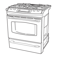
PGS908
MODEL NUMBER
OVEN CALIBRATION
Testing has shown that this oven has the best cooking performance at a control setting of 350°F
when the AVERAGE center oven temperature is between 350°F and 390°F. Customers may change
the average center oven temperature by ± 35°F to satisfy their own cooking needs.
To change:
• Press and hold BAKE and BROIL pads until “SF” appears in display.
• Press BAKE pad to enter oven calibration mode. “00” appears if oven calibration has not
been changed previously. If oven calibration has been changed previously, a temperature
between ± 35°F will be displayed.
• Press increase or decrease pads to change average oven temperature.
• Press START pad to return to Time of Day.
ERC FAILURE CODES
The oven may stop operating but not give an F code on the display immediately. F codes are stored
in nonvolatile eeprom memory until the same fault occurs twice consecutively. After that, the F code
will be displayed. F codes can be recalled by pressing together TIMER, CLOCK, MIN DOWN or 9.
While F codes are displayed, pressing MIN UP or 8 and HR DOWN or 6 together will clear them.
A fault must exist continuously for 5 minutes before an F code is recorded (F2 and F8 are sooner).
COLD START ODOR ADJUSTMENTS
NOTE: A small amount of odor is normal and will be present when the range is first turned on.
Also, adjustments require disassembly of the burner section. To prevent handling hot parts,
oven should be cool.
STEP 1: Remove oven door, oven
bottom, flame spreader (burner baffle),
orifice cover and oven burner. See below.
STEP 2: Closely Examine the Angle of
the Orifice. The orifice must point straight
into the burner. Check the angle by
looking at the orifice from above and from
the front. A socket Head Nut Driver may
be placed over the maintop orifice to help
determine any out of alignment condition.
The angle can be corrected by using a
small adjustment wrench clamped loosely
over the orifice to bend the orifice and its
mounting assembly as needed. See below.
STEP 3: Inspect the Primary Air Opening. The opening must be clear and free of insulation
all the way down to the metal shield below (0.314 inch opening). See above.
STEP 4: Using a drill bit as a gauge, adjust the air shutter opening.
COLD START ODOR ADJUSTMENTS
STEP 5: Examine the orifice cover. The cover must be as air-tight as possible. Bend the cover
to close off gaps between the sides and the top of the cover.
STEP 6: Install the oven door and observe the burner flame. Before installing the flame spreader
and oven bottom, close the oven door, set the control for BAKE and observe the burner flame.
Note: The door should remain closed during this test.
FLAME
SPREADER
ORIFICE COVER
OVEN BOTTOM
BURNER
FAILURE
CODE MEANING CORRECTION
Shorted OFF key
-F0-
Determine if problem is with key panel or control by
disconnecting ribbon cable and measuring flat cable
pins 13 to 14. Should be open. Should be 100–150
ohms while pressing OFF key.
Over temperature
1. Inside oven cavity as
measured by sensor
over 650°F unlatched
or 915°F latched
• Welded relay contacts
• Cooling fan stalled or blocked
• Airflow to rear of unit
• High resistance in oven sensor leads/connectors
(especially at sensor in rear)
-F3-
Open oven sensor (under
950 ohms)
• Disconnect power. Disconnect sensor harness from
control. Measure sensor resistance (white leads) to
be ~1080 ohms at room temperature with 2 ohms
per degree change.
• Look for damaged harness terminals if not a bad
sensor.
Shorted oven sensor
(over 2900 ohms)
• Disconnect power. Disconnect sensor harness from
control. Measure sensor resistance (white leads) to
be ~1080 ohms at room temperature with 2 ohms
per degree change.
• Separate sensor from harness to determine fault.
Shorted matrix or START
key
Determine if problem is with key panel or control by
disconnecting ribbon cable and measuring flat cable
using pinout chart. Allow up to 1000 ohms when
pressing a key.
-F2-
-F4-
-F7-
EEPROM data shift failure
If repeated, replace control.
Cooling fan or airflow to control area.
Cooling fan stalls while
above 650°F; open thermal
switch in yellow or blue leads
-F8-
-F9-
Loss of latch motor safety
circuit
Replace control.
-FF-
Observe the flames for a period of at least 2 minutes. The flame
should not “lift or blow off” the burner during any period of operation.
It should be blue with approximately a 1/2" to 3/4" inner cone.
LP Gas Installations: If flames lift off the burner and appear
unstable, reduce the air shutter openings an additional 1/32",
cool range and repeat Step 6 from a cold start. If flames are too
large but appear stable, check to be sure the range was properly
converted.
Natural Gas Installations: If flames are too large but appear stable,
tighten the orifice hood to reduce the gas flow to the burner.
1/2" To 3/4"
Inner Cone of Flame
Oven Broiler
Burner
REMOVABLE OVEN DOOR
COMPONENT COMPARTMENT AIRFLOW
The oven uses a fan for cooling the components. Air is pulled in by the fan blades and circulated in
the component compartment. The air is exhausted through louvers below the control panel and out
the slots above the door.
DOOR ASSEMBLIES:
The doors can be separated into two assemblies: (1) Outer assembly which consists of handle, vent
trim, outer glass, bottom trim and frame; (2) Inner assembly which consists of inner panel, gasket,
glass panels and insulation. The assemblies are held together by 2 screws on each side, along with
4 screws across the bottom.
CAUTION: Care must be taken when mounting door handle not to overtighten handle screws.
Overtightening screws can damage handle. Hand-tighten screws (do not use electric driver).
Make sure handle fits snugly to door panel.
SELF-CLEAN DOOR GASKET: The door gasket is attached to the inner door panel by a chain of
spring clips.
1. Locate spring clip at center of gasket and insert in hole on inner door panel near top.
2. Install gasket by bending at 90° beside clip and rocking into hole.
3. Tuck loose ends into slot at the bottom of inner panel.
STEP 7: Examine Flame Spreader for signs of warpage. If warped, spreader will have to be
replaced.
STEP 8: Install Flame Spreader and Oven Bottom. With customer present, test range from a cold
start to be sure odor problem has been corrected.
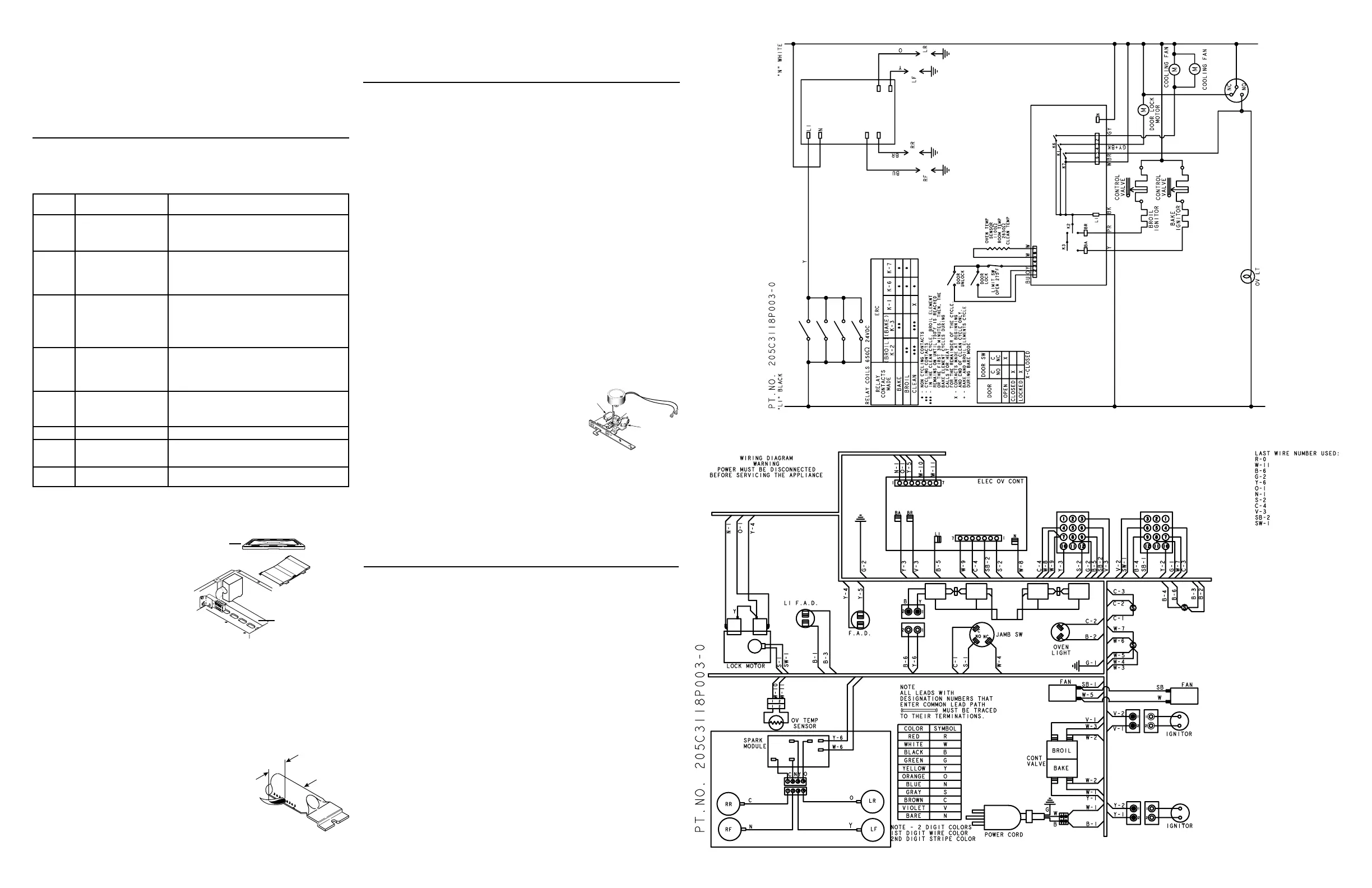
SELF-CLEAN & MOTORIZED DOOR LOCK
OPERATION LOCK CIRCUITS
There are two circuits controlling the locking and unlocking of the door. These are the lock motor
circuit and the lock switch circuit.
The lock motor circuit applies voltage (120 VAC) to the lock motor. This circuit is from L, through
the door switch, lock relay, lock motor to neutral. For this circuit to be complete, the lock relay must
be energized by the “B” control and the door must be closed. An open oven door results in “LOCK
DOOR” flashing in the display after the control has been programmed for clean and “START” has
been depressed.
The lock switch circuit “tells” the control if the lock motor is in the unlocked or locked position or
somewhere in between. There are two lock switches mounted to and operated by the lock motor.
The lock switch circuit is from the “B” control, through one of the lock switches (switch 2 for
unlocked or switch 1 for locked) back to the “B” control. If neither switch is closed, and the oven
temperature is below 600 degrees, the “B” control will energize the lock motor circuit until the correct
switch closes to complete the circuit. (If circuit to the correct switch is open, lock motor will run
continuously with the oven below 600 degrees.)
CLEAN CYCLE AND LOCK SEQUENCE
1. Program the Clean Cycle:
• Press “SELF-CLEAN” pad. 4 hours (4:00) appears on the time display. (Cleaning time can
be changed from the 4-hour starting point by pressing the “SELF-CLEAN” pad a second time.
• After “START” has been pressed, the word “ON” illuminates in red to indicate the cycle
has begun.
2. Locking the Door:
• After programming the clean cycle and pressing START pad, the control energizes the lock
relay. Voltage (120 VAC) is applied to the lock motor circuit. Oven door must be closed before
lock motor can run. “LOCK DOOR” will flash and control will beep until the door is closed.
• The lock motor begins to revolve and turns a cam mounted to the motor shaft.
• The words “LOCKED DOOR” will flash on and off on the display while the lock motor
is in motion.
• As the cam revolves about 1/2 revolution (approximately 12 seconds), it has moved the
lock “hook” into a corresponding slot in the oven door which secures the door.
• The movement of the cam has also closed lock switch 1 which “tells” the control the door is
locked. The control then removes power from the lock motor
circuit by de-energizing the lock relay.
• The lock motor stops and lock switch 1 is held closed by the
cam through the clean cycle.
• The words “LOCKED DOOR” stop flashing and remain
illuminated in the display.
• The word “ON” illuminates in the display.
3. During the Clean Cycle:
• The BROIL relay closes (audible “click”) and the broil burner
begins to heat. The broil burner only will operate during the first 30 minutes of the clean cycle
followed by the bake burner only during the remaining time.
• As the clean cycle progresses and the temperature of the oven control area rises, the cooling fan
is activated.
• A normally closed thermal switch is mounted on a bracket in front of the cooling fan. This switch
is in the lock switch circuit and will open the lock switch circuit in the event of an over-temperature
condition in the control area (caused by a stalled fan, fan switch failure or similar condition).
An -F2- (over-temperature) failure code will appear on the control if this switch opens while the
oven is above 600 degrees. With the oven between 400 to 600 degrees, the clean cycle will be
cancelled by the opening of the switch and the control will revert back to the time-of-day mode.
Below 400 degrees, the lock motor will revolve continuously and the words “LOCKED DOOR”
will flash on the control until the circuit is reestablished.
• The oven will cycle to maintain an average clean temperature of 840°F.
HTI
HTI Tech & Ind
HTSYG048B002FL45
-0001
Date:
Made in China
LOCK SW.
N.O. CONTACT
CLOSED
UNLOCK SW.
N.O. CONTACT
OPEN
CAM IN
LOCK POSITION
LOCKED
229C4059P559
 Loading...