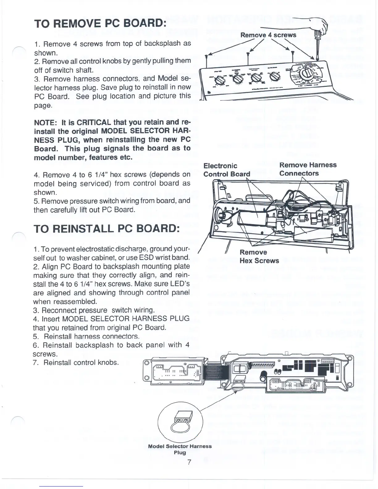
TO REMOVE PC BOARD:
1. Remove 4 screws from top of backsplash as
shown.
2. Removeallcontrol knobsbygentlypullingthem
oft of switch shaft.
3. Remove harness connectors, and Model se-
lector harness plug. Save plug to reinstall in new
PC Board. See plug location and picture this
page.
NOTE: It is CRITICALthat you retain and re-
install the original MODELSELECTOR HAR-
NESS PLUG, when reinstalling the new PC
Board. This plug signals the board as to
model number, features etc.
-~~~ ~
->,;;:j/.'-,-..' .~ ~
.. -----
Remove Harness
Connectors
Electronic
4. Remove 4 to 6 1/4" hex screws (depends on Control Board
model being serviced) from control board as
shown.
5. Removepressureswitchwiringfromboard,and
then carefully lift out PC Board.
TO REINSTALL PC BOARD:
1.To preventelectrostaticdischarge,ground your-
selfout to washercabinet,or use ESDwrist band.
2. Align PC Board to backsplash mounting plate
making sure that they correctly align, and rein-
stall the 4 to 6 1/4" hex screws. Make sure LED's
are aligned and showing through control panel
when reassembled.
3. Reconnect pressure switch wiring.
4. Insert MODEL SELECTOR HARNESS PLUG
that you retained from original PC Board.
5. Reinstall harness connectors.
6. Reinstall backsplash to back panel with 4
screws.
7. Reinstall control knobs.
Remove
Hex Screws
01 Ejj
~
. :::::::: .ii
.,.
01' .' ... .. ....
. ~ ~
Model Selector Harness
Plug
7
--
 Loading...