24
Installation Instructions
INSTALLATION—RECIRCULATING
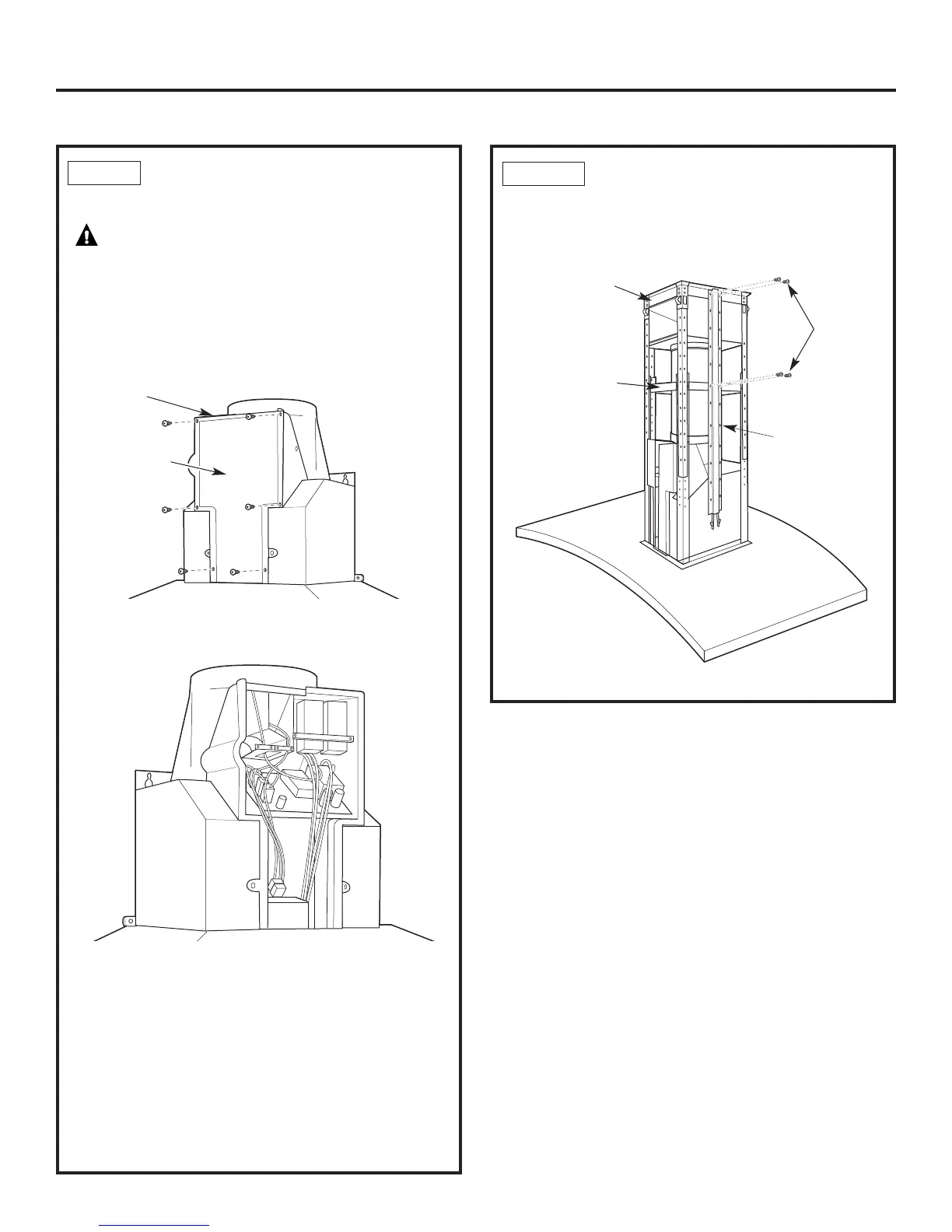
STEP 9 CONNECT ELECTRICAL
Verify that power is turned off at the source.
WARNING:If house wiring is not 2-wire
with a ground wire, a ground must be provided
by the installer. When house wiring is aluminum,
be sure to use U.L. approved anti-oxidant
compound and aluminum-to-copper connectors.
• Remove the 6 screws on the junction box cover
and the knockout on the top left side.
• Secure the house wiring to the junction box with
a strain relief (not provided).
• Connect the white lead to the branch circuit white lead.
• Connect the black lead to the branch circuit black lead.
• Connect the green/yellow lead to the branch
circuit green lead or bare ground lead.
• Secure all the connections with wire nuts on each
electrical connector.
• Push the wires into the junction box and replace
the cover. Be sure the wires are not pinched.
• Secure the junction box cover with the 6 original
screws.
STEP 10 INSTALL DUCT COVER SUPPORTS
• Attach the duct cover supports to the sides
of the horizontal and ceiling supports using
4 screws per duct cover support.
Junction
box cover
Knockout
Screws
Ceiling
support
Horizontal
support
Duct cover
support
 Loading...