DIAGNOSTIC STATUS CODES
SX TRANSISTOR CONTROL Page 24
Revised May 2003
TRACTION
STATUS CODE
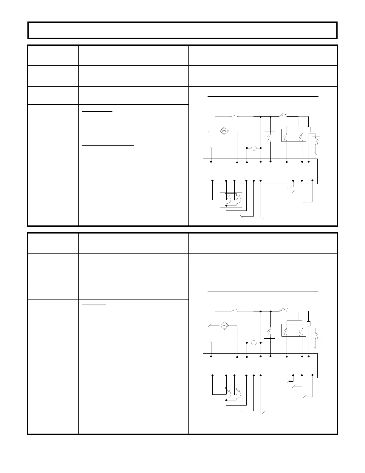
DESCRIPTION OF STATUS CAUSE OF STATUS INDICATION
-03
Standard truck configuration where
direction is set by accelerator volts –
reverse direction selected on power up.
This status code will be displayed when the voltage at
P7 is greater than 2.4V.
MEMORY RECALL
NO
CORRECTIVE ACTIONS TROUBLE-SHOOTING DIAGRAM
Circuits valid
for
Traction
Controller
SYMPTOM
Control will not operate because of
Static Return to Off (SRO) lock out.
POSSIBLE CAUSE
Accelerator calibration is incorrect and
it must be recalibrated for a new
accelerator pot installation.
· Repeat the accelerator pot
calibration routine outlined in this
operating manual
Defective control.
Replace the controller unit.
BDI INTERRUPT TO JOY
STICK CONTROLLER
*
TRACTION CONTROL PLUG PL-2
P10
P1
P7
P13
P9
ACCEL
SWITCH
P8
P20
TEMPERATURE INPUT FROM
PUMP CONTROL; OPEN INPUT
OR VOLTAGE > 3V = BDI
SIGNAL DISABLED
P14
TEMPERATURE SENSOR
INPUT FROM TRACTION
MOTOR
TACH SIGNAL
+12V TACH
P23P22
KEY SWITCH
*
DIRECT
SWITCH
P6
BRAKE SWITCH
*
L
P17 P2
*
SEAT SWITCH
P4 P5
*
FWD
REV
*
P18
*
24V
FAN
ENABLE
FAN
P21
NEG
PARK BRAKE SWITCH
*
2.2K
2W
TRACTION
STATUS CODE
DESCRIPTION OF STATUS CAUSE OF STATUS INDICATION
-03
Optional truck configuration with
directional switch input - reverse
directional switch is closed on initial
power up.
This status code will be displayed when P5 is greater
than 60% of battery voltage at initial key switch on.
MEMORY RECALL
NO
CORRECTIVE ACTIONS TROUBLE-SHOOTING DIAGRAM
Circuits valid
for
Traction
Controller
SYMPTOM
Control will not operate because of Static Return
to Off (SRO) lock out.
POSSIBLE CAUSE
Reverse directional switch is closed on initial
start up (i.e. closure of battery, key switch or
brake/deadman switch).
· Return directional switch lever to neutral and
then return lever to reverse position.
Reverse directional switch is welded closed or
mis-adjusted to be held closed.
· Replace or adjust directional switch to insure
that it opens when the directional switch is
returned to neutral.
Short circuit between B+ and P5.
· Disconnect the wire from P5 and check for a
voltage in the wire that was connected to P5.
If voltage is measured, locate and correct its
source.
Defective control. Replace the controller unit.
BDI INTERRUPT TO JOY
STICK CONTROLLER
*
TRACTION CONTROL PLUG PL-2
P10
P1
P7
P13
P9
ACCEL
SWITCH
P8
P20
TEMPERATURE INPUT FROM
PUMP CONTROL; OPEN INPUT
OR VOLTAGE > 3V = BDI
SIGNAL DISABLED
P14
TEMPERATURE SENSOR
INPUT FROM TRACTION
MOTOR
TACH SIGNAL
+12V TACH
P23P22
KEY SWITCH
*
DIRECT
SWITCH
P6
BRAKE SWITCH
*
L
P17 P2
*
SEAT SWITCH
P4 P5
*
FWD
REV
*
P18
*
24V
FAN
ENABLE
FAN
P21
NEG
PARK BRAKE SWITCH
*
2.2K
2W

 Loading...


