DIAGNOSTIC STATUS CODES
SX TRANSISTOR CONTROL Page 26
Revised May 2003
TRACTION
STATUS CODE
DESCRIPTION OF STATUS CAUSE OF STATUS INDICATION
-09
Optional truck configuration - both the
forward and reverse directional
switches are closed at the same time.
This status code will be displayed when P4 and P5
are greater than 60% of battery volts at the same
time.
MEMORY RECALL
NO
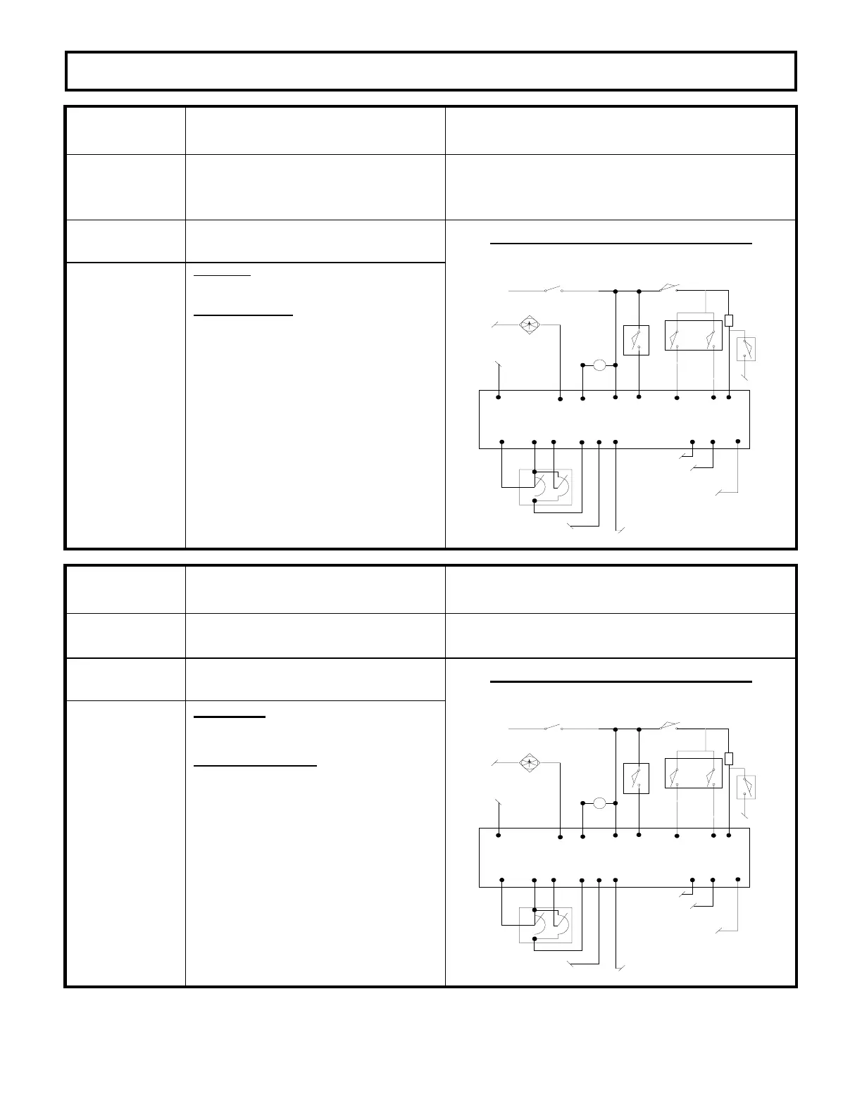
CORRECTIVE ACTIONS TROUBLE-SHOOTING DIAGRAM
Circuits valid
for
Traction
Controller
SYMPTOM
Control will not operate.
POSSIBLE CAUSE
Forward or reverse directional switch welded
closed or mis-adjusted to be held closed.
· Replace or adjust directional switches to
insure that they open when directional switch
is returned to neutral.
Short circuit between battery positive and P4
and/or P5.
· Disconnect wires from P4 and P5 and check
wire for short circuit to positive side of
directional switch.
Defective Control
· Disconnect wires and measure voltage at P4
and P5. Voltage should be less than 60% of
battery volts.
BDI INTERRUPT TO JOY
STICK CONTROLLER
*
TRACTION CONTROL PLUG PL-2
P10
P1
P7
P13
P9
ACCEL
SWITCH
P8
P20
TEMPERATURE INPUT FROM
PUMP CONTROL; OPEN INPUT
OR VOLTAGE > 3V = BDI
SIGNAL DISABLED
P14
TEMPERATURE SENSOR
INPUT FROM TRACTION
MOTOR
TACH SIGNAL
+12V TACH
P23P22
KEY SWITCH
*
DIRECT
SWITCH
P6
BRAKE SWITCH
*
L
P17 P2
*
SEAT SWITCH
P4 P5
*
FWD
REV
*
P18
*
24V
FAN
ENABLE
FAN
P21
NEG
PARK BRAKE SWITCH
*
2.2K
2W
TRACTION
STATUS CODE
DESCRIPTION OF STATUS CAUSE OF STATUS INDICATION
-11
Accelerator volts too low on power up. This status code will be displayed when accelerator
volts are less than 1.7V at P7.
MEMORY RECALL
NO
CORRECTIVE ACTIONS TROUBLE-SHOOTING DIAGRAM
Circuits valid
for
Traction
Controller
SYMPTOM
Control will not operate.
POSSIBLE CAUSE
Defective accelerator pot.
· Measure the voltage from P9 to
NEG. Voltage should be between
4 to 4.8 volts. If not, disconnect
the wire from P9. Measure the
voltage from P9 to NEG. This
voltage should be greater than 4
volts; if not, replace the control.
· Disconnect wire from P7. Measure
voltage from the wire removed from
P7 to NEG. Voltage should be
greater than 1.9V, if not, replace
accelerator pot.
BDI INTERRUPT TO JOY
STICK CONTROLLER
*
TRACTION CONTROL PLUG PL-2
P10
P1
P7
P13
P9
ACCEL
SWITCH
P8
P20
TEMPERATURE INPUT FROM
PUMP CONTROL; OPEN INPUT
OR VOLTAGE > 3V = BDI
SIGNAL DISABLED
P14
TEMPERATURE SENSOR
INPUT FROM TRACTION
MOTOR
TACH SIGNAL
+12V TACH
P23P22
KEY SWITCH
*
DIRECT
SWITCH
P6
BRAKE SWITCH
*
L
P17 P2
*
SEAT SWITCH
P4 P5
*
FWD
REV
*
P18
*
24V
FAN
ENABLE
FAN
P21
NEG
PARK BRAKE SWITCH
*
2.2K
2W

 Loading...


