DIAGNOSTIC STATUS CODES
SX TRANSISTOR CONTROL Page 27
Revised May 2003
TRACTION
STATUS CODE
DESCRIPTION OF STATUS CAUSE OF STATUS INDICATION
-12
One or both accelerator pots are
defective when the control is
configured for dual pot input.
This status code will be displayed when the sum of
the voltages of the two pots is greater than 5V or less
than 4V.
MEMORY RECALL
YES
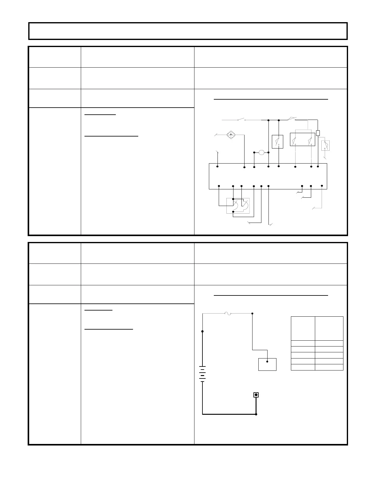
CORRECTIVE ACTIONS TROUBLE-SHOOTING DIAGRAM
Circuits valid
for
Traction
Controller
SYMPTOM
Control will not operate.
POSSIBLE CAUSE
Defective accelerator pot.
· Measure the voltage from P9 to P8.
Voltage should be between 4 to 4.8
volts. Voltage from P7 to NEG
should be approximately 2.14 V.
Connect the voltmeter from P7 to
P13. The voltage measured should
equal 0 to +/- 0.25V. Connect the
voltmeter to the wire removed from
P7. Connect the voltmeter negative
to the wire removed from P13. The
voltmeter should read greater than
4V, but less than 5V. If not,
replace
the potentiometer.
BDI INTERRUPT TO JOY
STICK CONTROLLER
*
TRACTION CONTROL PLUG PL-2
P10
P1
P7
P13
P9
ACCEL
SWITCH
P8
P20
TEMPERATURE INPUT FROM
PUMP CONTROL; OPEN INPUT
OR VOLTAGE > 3V = BDI
SIGNAL DISABLED
P14
TEMPERATURE SENSOR
INPUT FROM TRACTION
MOTOR
TACH SIGNAL
+12V TACH
P23P22
KEY SWITCH
*
DIRECT
SWITCH
P6
BRAKE SWITCH
*
L
P17 P2
*
SEAT SWITCH
P4 P5
*
FWD
REV
*
P18
*
24V
FAN
ENABLE
FAN
P21
NEG
PARK BRAKE SWITCH
*
2.2K
2W
TRACTION
STATUS CODE
DESCRIPTION OF STATUS CAUSE OF STATUS INDICATION
-15
Battery voltage is too low or control
card is mis-adjusted.
This status code will be displayed when the battery
volts are less than 1.95 volts per cell at initial key
switch on. See table below.
MEMORY RECALL
NO
CORRECTIVE ACTIONS TROUBLE-SHOOTING DIAGRAM
Circuits valid
for
Traction
Controller
SYMPTOM
Control will not operate.
POSSIBLE CAUSE
Discharged battery
· Check battery for proper open circuit
voltage as shown in “Trouble Shooting
Diagram”, charge battery, if required.
Defective battery
· Check each battery cell for proper
voltage (greater than 1.95 volts at cell).
Replace or repair battery.
Incorrect control card adjustment.
· Check Function 15 for proper adjustment
for battery being used. See Handset
instruction sheet for details. Adjust to
proper settings.
Check “minimum” battery volts at P1 and
NEG.
NEG
+
-
FU5
P1
NOMINAL
BATTERY
VOLTAGE
MINIMUM
LIMIT VOLTS
AT 1.95 VDC
PER CELL
24
80
48
72
36
23.4
78.0
46.8
70.2
35.1

 Loading...


