342-86400-431PS
Issue 2.1
March 2013
Page 8
Copyright
GE Multilin Inc. 2001-2013
3. FRONT PANEL LAYOUT
(B)86431-0X Power Unit
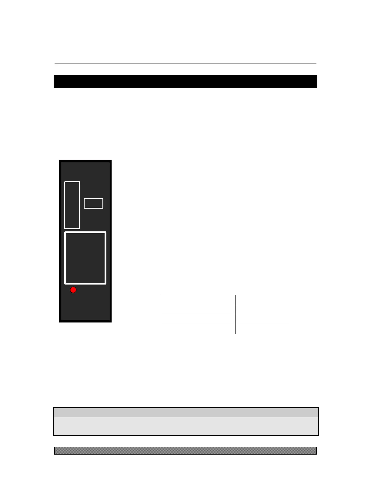
A front panel layout for a (B)86431-0X unit is shown in Figure 1 (the figure
specifically shows the layout for the 130VDC option). The Power Unit does not
come equipped with a CI (Craft Interface) since there are no software-adjustable
parameters.
Alarm LED (Red)
This LED provides a visual indication of the unit's status.
The LED will light in a protected system (i.e. two or more
Power Units in parallel) if the fuse opens or the station
battery is removed. The LED will also light if the internal
DC-to-DC converter fails.
Fuse
The (B)86431-0X unit uses a fast-acting GMT fuse in line
with the main battery input. The fuse protrudes through the
faceplate so it can be installed or removed from the front.
The fuse rating depends on the unit option as shown in the
table below.
Extractor
Located at the bottom of the unit's face plate is the extractor, which is an integral
part of the unit's casing. As the name implies, it allows for easy extraction of the
unit from the shelf.
WARNING
Do not use the extractor to force the unit into the shelf as this could
result in damage to the extractor.
B86431-03 (130V)
BEFORE
POWER
UNIT
ALARM
INSERTING
UNIT
REMOVE
FUSE
CAUTION
0.5 A
LENTRONICS
MULTIPLEXERS
Figure 1:
B86431-03 Front
Panel Layout