Install Modules
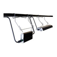
Typical layout
Using the diagram below as an estimation guide, begin cutting strings of modules to create 8-inch (203 mm) tall
rows and 12-inch (305 mm) wide columns.
Lay modules into the application at least 2 inches
(51 mm) from the edges.
Start another row with 2.77-inch (70 mm) spacing
between the module strings.
2
1 2
Modules should be 2 inches (51 mm) from the edge of the application with 2.77 inches (70 mm) between
each column.
12” (305 mm)
wide columns
2” (51 mm)
from edge
2” (51 mm)
from edge
2” (51 mm)
from edge
8” (203 mm)
tall rows
2.77” (70 mm)
between
columns
2.77” (70 mm)
between columns
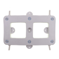
Fasten down each module with at least one screw
in the center hole or two opposing sides.
Continue this process until the entire application is
populated with modules.
 Loading...