EasyManua.ls Logo

GE Arize Element L1000 Gen2 User Manual

GE Arize Element L1000 Gen2
27 pages
Go to English
To Next Page IconTo Next Page
Page #1 background imageLoading...
Page #1 background image
Arize Element
®
L1000 Gen2
Horticulture LED Lighting System
HORT162 | DOC-xxxxxxx
WARNING
RISK OF ELECTRIC SHOCK
Turn power o before inspection, installation or removal.
Properly ground electrical enclosure.
RISK OF FIRE
Follow all IEC and local building codes.
Use only IEC approved wire for input/output connections.
Minimum size 3G 0.75mm
2
.
Minimum 300mm distance from light module & driver to any
combustible material.
Minimum 150mm clearance between light module & driver, light
module & light module, driver & driver.
The light module shall be installed lens down with a minimum of
130mm to anything below.
CAUTION
Do not operate the product with damaged parts.
Turn o power before inspection, installation or removal.
Luminaire may fall down if not installed properly.
Wear work gloves to prevent dirt and oil from being transferred to
the luminaire.
Not for direct exposure to the weather.
To ensure the product warranty is valid, please ensure all installation
instructions and environmental conditions for storage and operation
are complied with.
The light source of this luminaire is not replaceable; when the light
source reaches its end of life the whole luminaire shall be replaced.
Use only in the manner intended by the manufacturer. If you have
any questions, contact the manufacturer.
For safe operation, and to maximize the longevity of the luminaire;
ensure that the light module and driver are clean and free of dirt,
dust, oil, or any other debris.
Do not apply any kind of lm on the lens or otherwise cover the
driver or light engine in any way.
The external exible cable or cord of this luminaire cannot be
replaced; if the cord is damaged, the luminaire shall be destroyed.
Part Number
220–240 VAC
Power (W)
380–415 VAC
Power (W)
Risk
Group
Min. Viewing
Distance (m)
GEHE-HPPRB2A 585 589 2 5.2
GEHE-HPPBB2A 622 626 2 5.2
GEHE-HPKTB2A 606 610 2 5.2
GEHE-HPKRB2A 623 628 2 5.2
GEHE-HPKBB2A 639 643 2 5.2
GEHE-HPKFB2A 643 647 2 5.2
GEHE-HBRIB2A 656 660 2 5.2
GEHE-HBRVB2A 681 684 2 5.2
GEHE-VPPRB2A 530 533 2 5.2
GEHE-VPPBB2A 575 580 2 5.2
GEHE-VPKTB2A 538 542 2 5.2
GEHE-VPKRB2A 569 573 2 5.2
GEHE-VPKBB2A 590 594 2 5.2
GEHE-VPKFB2A 570 575 2 5.2
0°C
40°C
Suitable for operation in an ambient temperature
between 0°C and 40°C.
A mechanical ventilation or cooling system is
required to maintain the temperature within the
growing space below 40°C when the light module
is in operation.
IEC/TR 62778 Risk Group 2 (RG2)
DA
Installationsvejledning
DE
Einbauanleitung
ES
Guía de instalación
FI
Asennusohje
FR
Guide d’installation
HU
Felszerelési útmutató
IT
Guida all’installazione
LT
Sumontavimo vadovas
NL
Installatiehandleiding
NO
Monteringsanvisning
PL
Instrukcja instalacji
PT
Guia de Instalação
SE
Installationsguide
220-240V
50-60Hz
380-415V
50-60Hz
IP66
The LED luminaire must be connected to
the mains supply according to its ratings on
the product label.
Question and Answer IconNeed help?

Do you have a question about the GE Arize Element L1000 Gen2 and is the answer not in the manual?

GE Arize Element L1000 Gen2 Specifications

General IconGeneral
BrandGE
ModelArize Element L1000 Gen2
CategoryLighting Equipment
LanguageEnglish

Summary

Safety and Warnings

Electrical Shock and Fire Risks

Details critical safety precautions regarding electrical shock and fire hazards during installation and operation.

General Cautions and Handling

Provides important cautions for product handling, installation, and maintenance, including protective gear.

Product Specifications

System Component Parts

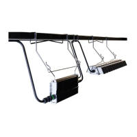
Lists and illustrates the main components included in the Arize Element L1000 Gen2 lighting system.

Light Module Specifications

Details technical specifications for various light module part numbers, including current and power factor.

Driver Specifications

Outlines the specifications for the associated drivers, including weight and input voltage compatibility.

Cables and Accessories

Interconnection Cable Specifications

Provides details on various interconnection cables, including length, type, and certifications.

Mounting Accessories Specifications

Lists and specifies different mounting kits and accessories available for the lighting system.

Light Module Installation

Installation of Module Brackets

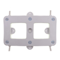
Instructions for attaching mounting brackets to the light module, ensuring secure attachment.

Selection of Mounting Hardware

Guidance on selecting appropriate hangers or mounting cables based on structural member type.

Installation with Standard and Offset Hangers

Steps for installing the light module using standard or offset hangers on structural members.

Installation with Universal Cables

Procedure for mounting the light module using universal loop and hook cable systems.

Installation with Perpendicular 90° Universal Mounting Kit

Detailed steps for using the 90° universal mounting kit for secure fixture installation.

Installation with Custom Brackets

Instructions for attaching the light module using custom mounting methods at designated points.

Driver Installation

Installation of Driver Bracket

Steps to correctly attach the mounting bracket to the driver unit for secure mounting.

Selection of Mounting Hardware

Guidance on choosing hangers or cables for mounting the driver based on structural member type.

Installation with Hangers

Process for hanging the driver module onto structural members using appropriate hanger brackets.

Installation with Universal Cables

Method for mounting the driver using universal cables, involving loops and hooks.

Installation with Custom Brackets

Instructions for attaching the driver using custom mounting solutions at specific points.

Electrical Connections

Connect Driver Output to Light Module

Procedure for connecting the driver's output to the light module cable, ensuring a secure click.

Connect the Driver Input

Steps for connecting the driver's power input using leader cables, including connector alignment.

Using Custom AC Inputs

Guidance for connecting custom AC input connectors to the driver unit.

Connecting Driver to AC Line

Instructions on wiring the driver to the incoming AC power line, specifying conductor connections.

Connection Schematic

Diagram illustrating the overall electrical connection schematic for the lighting system.

Optional Wired Dimming

Connecting Wired Dimming

Instructions for connecting the optional wired dimming control to the driver unit.

Save These Instructions

Related product manuals