13
Arize Element
®
L1000 Gen2 Installation Guide
3.3 Connection Schematic
4 Connecting Wired Dimming (Optional)
Driver Input Wire
Colors
Brown = Line 1
Blue = Neutral or Line 2
Yellow/Green = Ground
Light module
AC line
Use proper circuit
protection level
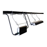
Optional 914 mm or 1828 mm inter-connection cable
NOTE: Maximum cumulative length of inter-connection cable is 3.6 m.
Driver
*Blue = Neutral or Line 2
* * *
Driver Driver Driver Driver
N
3-Phase Y
REPEAT FOR ENTIRE CIRCUIT BALANCING OUT EACH PHASE
3-Phase ∆
L3
L2
L1
Driver Driver
Green
Green
Green
Green
Green
Green
Brown
Brown
Brown
Brown
Brown
Brown
Blue
Blue
Blue
Blue
Blue
Blue
Dimming
Cable
Purple
Black/White (12V)*
Pink
Dimming
Switch
+ (0-10V)
- (0-10V)
WARNING
RISK OF ELECTRIC SHOCK
Turn power o before installation, inspection, cleaning or removal. And follow appropriate lock out/tag out safety procedure.
WARNING
Ambient temperature surrounding
each driver must be lower than 40°C.
Remove cap from dimming
connector.
Plug dimming cable: align
keying features and push
connectors together until lock
ring has snapped into place
and a click is heard. To remove
dimming cable, turn locking ring
1/8 of a turn counter-clockwise
and separate connectors.
Connect the appropriate wiring
to Dim + (0-10V) and Dim –
(0-10V) from driver. Insulate
the black wire. Follow dimming
switch instructions for rest of
connection.
*The black/white wire is a 12V
auxiliary output that can support
up to 250mA of current.
1 2 3
 Loading...