10 49-2000894 Rev. 3
Installation Preparation
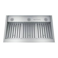
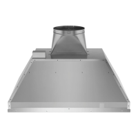
PRODUCT DIMENSIONS
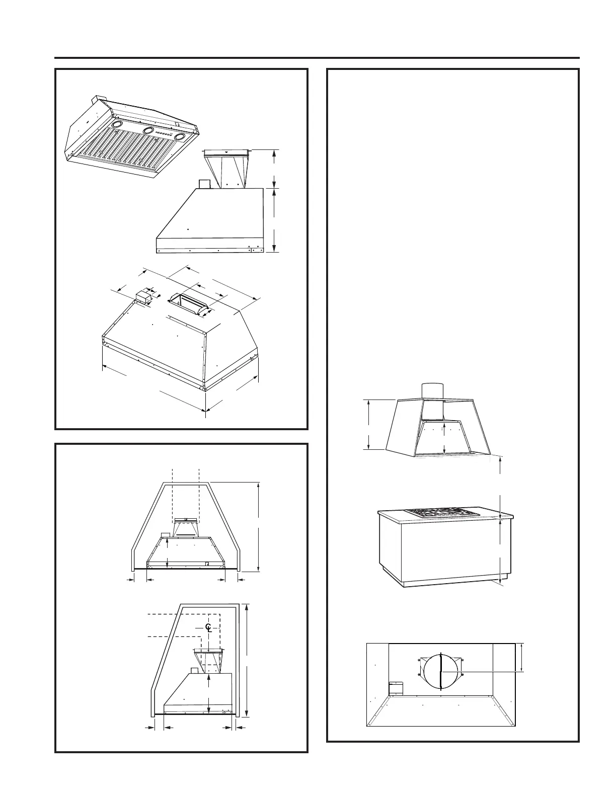
INSTALLATION PREPARATION
CABINET PREPARATION
12"
19-1/8"
18" or 24"
28-1/4" or
34-1/4"
4-1/4"
9"
1-15/16"
3-1/8"
1" 1"
11-1/2"
FRONT VIEW
18-1/2" min.
6-15/16"
11-1/2"
3" 1"
SIDE VIEW
11-1/2"
29" min.
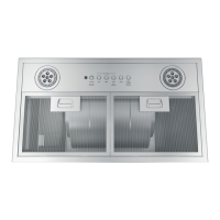
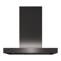
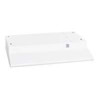
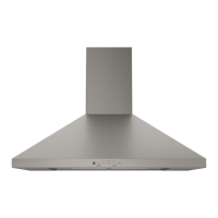
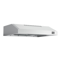
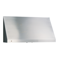
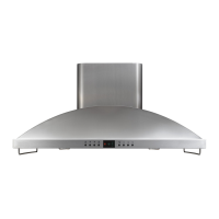
Design varies by model
INSTALLATION CLEARANCES
This vent hood must be installed between the 24"
required minimum and 36" recommended maximum
above the cooking surface.
Ŷ$OZD\VUHIHUWRWKHFRRNWRSRUUDQJHLQVWDOODWLRQ
instructions for product-specific clearances.
NOTE: Installation height should be measured
from the cooking surface to the bottom edge of the
cabinet surface.
NOTE: UL requires any combustible surface to be a
minimum of 30" above the cooking surface. Lower
combustible surfaces may be covered to meet
requirements.
Ŷ7KHFXVWRPFDELQHWLQWHUQDOKHLJKWPXVWEH
18-1/2" minimum for vertical venting and 29"
minimum for recirculation.
Ŷ7KLVKRRGFDQEHYHQWHGWRWKHRXWGRRUVRULW
can be installed for recirculating operation. For
recirculating operation, refer to Recirculating
Installation Planning.
Ŷ7KLVKRRGPD\EHPRXQWHGLQDZDOOFDELQHWRU
installed over an island.
NOTE: The exhaust duct on the hood is closer to
the rear of the hood. It is important to plan for the
alignment to the connection point of the hood.
*24" Minimum required
*36" Maximum recommended
Typically 36"
18-1/2" min.
11-1/2"
6-1/2"
1" = 2.5 cm
 Loading...