Do you have a question about the GE VE1012 Series and is the answer not in the manual?
Title of the installation sheet for the VE1012 Series PIR Detector.
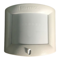
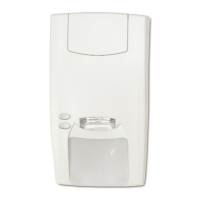
Visual guides illustrating installation scenarios and jumper configurations.
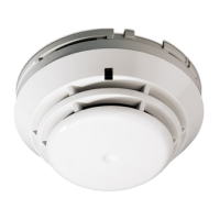
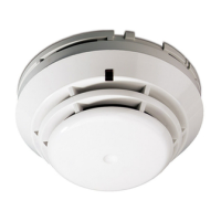
Overview of VE1012 series PIR and PIR-AM detectors and their technology.
Guidelines to prevent false alarms and ensure stable detector performance.
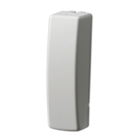
Steps and considerations for physically mounting the detector on a wall.
Explanation of jumper functions for PIR enabling, dual loop, D/N mode, and polarity.
Configuration options for AM/TF signaling, AM sensitivity, and AM/TF reset.
Description of LED behavior during startup, low voltage, and alarm events.
| Category | Security Sensors |
|---|---|
| Manufacturer | GE Security |
| Mounting | Surface Mount |
| Color | White |
| Output Type | Normally Closed (NC) |
| Sensitivity Adjustment | No |
| Operating Temperature | -40°F to 149°F |
| Housing Material | Plastic |
| Gap | 0.5 inch (12.7 mm) |
| Dimensions | 1.5 x 0.75 x 0.5 inches (38 x 19 x 12.7 mm) |