Do you have a question about the GE Vivid 3N Pro Series and is the answer not in the manual?
This chapter describes important issues related to safely servicing the Vivid 3N scanner.
Conventions used in this manual, including safety precaution messages and icons.
Safety precautions to be observed during all phases of operation, service and repair.
Warnings that precede potentially dangerous procedures throughout this manual.
Labels and icons found on the Vivid 3N Pro/Expert ultrasound unit.
Description of labels and symbols found on the Vivid 3N Pro/Expert ultrasound unit.
Additional labels found on the Vivid 3N Pro/Expert ultrasound unit.
Information on Electromagnetic Compatibility, Interference, and Electrostatic Discharge.
Relevant EC directives and European Harmonized/International standards used.
Information on how to contact GE for assistance.
Information required to plan and prepare for the installation of a Vivid 3N Pro/Expert unit.
Details on environmental, cooling, lighting, and time/manpower requirements for the console.
Requirements for dedicated power and Ground for proper operation of the ultrasound equipment.
Recommendations for preventing Electromagnetic Interference (EMI) issues.
Operational and storage temperature requirements for probes.
Work and materials required to prepare the site, purchaser responsibilities.
Mandatory requirements for the site installation of the ultrasound unit.
Optional site recommendations for ultrasound room layout.
Requirements for connecting the unit to a network.
Information required to configure the unit for network connections.
Worksheet to record connectivity installation details.
Checklist to verify all required steps have been completed before installation.
Instructions for installing the Vivid 3N Pro/Expert ultrasound unit.
Average installation time and warnings for system installation.
Procedures for receiving and unpacking the ultrasound unit.
Information on tilt and shock indicators attached to the transportation box.
Procedure to examine all packages closely at time of delivery.
Procedure to follow if damage is apparent or indicators show failure.
Instructions for unpacking the Vivid 3N Pro/Expert unit.
Verification of the contents of the accessory box.
Steps to prepare for the installation process.
Inspection of system components using the supplied checklist.
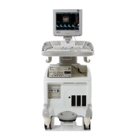
Illustration of visible components from the front and side.
Description of the three-position foot brake.
Procedure for connecting and configuring the configurable footswitch.
Verification of scanner's set voltage and configuration.
Configuration of the scanner and VIC for PAL or NTSC video systems.
Measures to protect the system from Electromagnetic Interference (EMI).
Steps to complete the hardware installation of the ultrasound unit.
Connection of peripheral devices like VCR or printer to the unit.
Procedure for connecting the VCR and configuring its settings.
Procedure for connecting the B&W printer.
Procedure for connecting the color printer.
Procedure for installing the DeskJet Color Printer.
Instructions for connecting probes to the ultrasound unit.
List of probes available for use with the Vivid 3N Pro/Expert unit.
Procedure for connecting the internal ECG to the patient trace (I/O) panel.
Procedure for connecting the unit to a power source.
Procedure for connecting the ultrasound unit to the electrical outlet.
Procedure for disconnecting the ultrasound unit from the electrical outlet.
Procedures for switching the system ON and OFF.
Procedure for installing application and operating system software.
Configuration of system settings in the System Configuration window.
Steps for connecting the system to various connectivity devices.
Precautions for avoiding equipment damage and ensuring safety during transport.
Recording relevant system installation details and product locator information.
Locating and filling details on Product Locator Installation Cards.
Functional checks for installation, servicing, and periodic maintenance.
Procedures for power ON/OFF and boot-up tests.
Basic checks of controls, including keyboard and footswitch tests.
Tests for VCR, Printers, and other peripheral devices.
Image quality tests for various probes.
Checks to be performed before returning the scanner to regular operational use.
Block diagrams and functional explanations of the Vivid 3N electronic circuits.
Description of the Vivid 3N as a phased, linear array ultrasound imaging scanner.
System block diagrams including RFI and RFT configurations.
Includes boards in the Front End Card Cage and their functions.
Description of components supporting the unit's operation and acting as the main controller.
List of external peripherals used with the Vivid 3N ultrasound scanner.
Explanation of how AC voltage is converted to internal DC voltages for system components.
Components of the AC system, including isolation transformer and distribution box.
Description of the cooling system components and airflow within the unit.
Software modules common to GE ultrasound and cardiology systems.
Purpose of Chapter 6, covering service adjustments.
Configuration of input AC voltage settings for the system.
Status indication via LEDs on various boards in the Front End Crate.
LEDs on the Mother Board indicating status of voltages in the Back End.
Configuration of the scanner and VIC for PAL or NTSC video systems.
Adjustments for monitor settings including Geometry and Image Quality.
Calibration of image quality related settings for the monitor.
Procedures for performing monitor, beamformer, and video grabbing calibration.
Describes how to set up and run diagnostic tools to locate system problems.
Overview of diagnostic tools and procedures for identifying and correcting problems.
Tests for FE circuits and boards, including Auto Sequence and manual options.
Testing the functionality of various Back End hardware components.
Access to common service components and diagnostics via a web-controlled interface.
Access to common service components and diagnostic tests.
Page for verifying and calibrating image quality.
Page for performing different calibration procedures.
Page to configure the GSUI (InSite).
Access to various Windows 2000 utility tools for system status indication.
Page for part replacement details and ordering information.
Page for planned, proactive and preventive maintenance information.
Automatic logging of software activity, sequences, and error messages.
Purpose of Chapter 8, providing replacement procedures for system parts.
Procedures for removing and replacing various covers of the unit.
Replacement procedures for components within the control console.
Instructions for replacing Front End boards.
Procedures for replacing internal Back End Processor components.
Procedures for replacing components in the lower section of the unit.
Installation and removal procedures for external peripherals.
Purpose of Chapter 9, providing an overview of replacement parts.
List of abbreviations used in the manual.
Details of optional service parts kits.
Overview of the AC power system and its components.
List of parts for the control panel.
List of replacement parts for the Front End.
Information about the Global Modem.
List of replacement parts for the Back End.
Renewal parts related to the ECG module.
List of manuals and software versions.
Information on software versions and kits.
List of available probes for the Vivid 3N Pro/Expert ultrasound unit.
List of approved peripherals for the system.
Diagram illustrating the system cabling for BT02/BT03 configurations.
Diagram illustrating the system cabling for BT’01 configuration.
Diagram illustrating the system cabling for BT’00 configuration.
Describes Periodic Maintenance (PM) procedures for the Vivid 3N Pro/Expert unit.
Safety warnings related to maintenance procedures.
Importance of maintaining records and quality assurance for the system.
Schedule specifying frequency of PM procedures and items requiring attention.
List of special tools, supplies, and equipment for periodic maintenance.
Preliminary checks for system periodic maintenance.
Checks to verify basic operation of system modes and controls.
Checks for installed peripherals and options.
Procedures for inspecting mains cable and connectors.
Instructions for general cleaning and air filter cleaning.
Checks for labeling, physical condition, and operation of components.
Performing diagnostic tests to complete periodic maintenance checks.
Procedures for probe care, handling, cleaning, and sterilization.
Guidelines for returning and shipping defective probes.
Electrical safety evaluation of cord-connected, electrically operated equipment.
Current leakage limits summarized for NFPA 99 and IEC 60601-1 standards.
Testing outlets for proper grounding and wiring arrangement.
Procedure to measure resistance from the third pin to exposed metal parts.
Measures current flow to Ground if the Ground wire breaks.
Measures current flow to Ground from isolated ECG leads.
Performs isolation test on leads.
Measures current flow to Ground from probes.
Procedure to test each transducer for leakage current without a meter adapter.
Data sheet for recording chassis source current leakage test results.
Data sheet for recording ECG current leakage test results.
Data sheet for recording transducer source current leakage test results.
Certificates for Periodic Maintenance and Safety Inspections.
| Brand | GE |
|---|---|
| Model | Vivid 3N Pro Series |
| Category | Medical Equipment |
| Language | English |