EasyManuals Logo

GE Vivid E95 Technical Publication

GE Vivid E95
127 pages
To Next Page IconTo Next Page
To Previous Page IconTo Previous Page
Page #102 background imageLoading...
Page #102 background image
Care and Maintenance
4-24 Ultrasound SystemCommon Service Information
Direction 5444964-100 English
Rev. 5
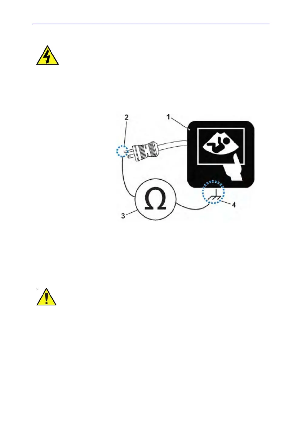
Grounding continuity
Measure the resistance from the third pin of the attachment plug
to the exposed metal parts of the case. The ground wire
resistance should be less than 0.2 ohms. Reference the
procedure in the IEC60601-1-1 and/or IEC62353.
Figure 4-2. Ground continuity test
DANGER Electric Shock Hazard!
The patient or operator MUST NOT come into contact with the equipment
during this test.
1. Ultrasound System
2. Ground Pin
3. Ohmmeter or Electrical Safety
Analyzer
4. Accessible Metal Part such as:
• Potential equilibrium connector
• Monitor housing
• Probe connector
CAUTION
Lacquer is an isolation barrier! Measure only on blank
accessible metal parts.

Table of Contents

Other manuals for GE Vivid E95

Questions and Answers:

Question and Answer IconNeed help?

Do you have a question about the GE Vivid E95 and is the answer not in the manual?

GE Vivid E95 Specifications

General IconGeneral
TypeCardiovascular Ultrasound System
Transducers2D, 3D, 4D
Display22-inch high-resolution OLED monitor
PortabilityCart-based
Imaging Modes2D, 3D, 4D, Color Doppler
Advanced FeaturescSound Architecture
ConnectivityDICOM, USB, Ethernet
ApplicationsCardiology, Vascular, Abdominal

Related product manuals