11
geappliances.com
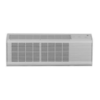
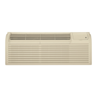
System Essential Components and Installation
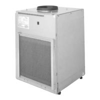
Unit including sleeve and
front panel
The unit is packaged with the
case and the front panel in place
(filter not included). Installation
begins by removing the front
panel and pulling the unit out
of the case. The empty case is
positioned on the platform in
the closet with the outdoor side
facing the wall plenum opening
(remove the side panel if a side installation is to be made) and
secured to the plenum with six field supplied screws (stainless
recommended).
Level the case using the four leveling legs and, using the holes
in the bottom of the case as guides, drill holes in the mounting
platform to secure the case to the platform. Use four field-
supplied bolts, washers and nuts to secure the case to the
mounting platform. Do not tighten the bolts to the point of
distorting the case.
Failure to secure the case to the platform may result in
excessive unit vibration and increased noise level. Install
the unit into the case, either through the front or side panel
opening. With the unit in position in the case, replace the side
panel (if removed) and the front panel. Ground the unit to the
case by installing the front unit-to-case hex bolt and/or the
case-to-unit side screw (only on side installs).
The drain connection is made by connecting a 90
o
PVC
elbow to the unit’s female 3/4" NPT drain connector. The other
end of the elbow is used to run the drain to either the internal
or external drain.
The unit is shipped with a secondary drain hole. This drain hole
is shipped open and must either be plugged or connected to
an independent drain system. If a secondary drain system is
used, attach a 90° schedule 40 PVC elbow to the secondary
drain hole directed toward the secondary drain system. If a
secondary drain system is NOT used, install a 3/4" schedule
40 PVC plug to cap the hole. Ensure drain lines going out the
plenum are sloped downward to allow water to drain out.
A 10" diameter flange on the top of the unit is used to connect
to field supplied, insulated, flexible or rigid transition duct with
an adjustable ring clamp.
Flexible duct may be used for transitions only. Rigid duct must
be used for 90
o
bends and tees. Do not use flexible duct for
unsupported runs of five feet or more.
Power Connection Kit
The ZVAC units have a universal heater assembly that is
capable of producing electric resistance heat that can operate
on a 15-amp, 20-amp, or 30-amp circuit. The amount of
resistance heat is determined by the selection of the correct
power connection kit. This is the same type of connection
used by GE for years in the Premium and Deluxe series of the
Zoneline units.
Units installed on 230 or 208-volt circuits may be line cord
connected by plugging the line cord into a wall-mounted
receptacle in the enclosure closet or directly connected.
All ZVAC units come with a unit mounted junction box
to contain the wiring connections if a direct connection
installation is required. The same power connection kit is
used for line cord connection or to make a direct connection.
Instructions for making a direct connection on 230 or 208-volt
circuits are included in the unit installation instructions.
Units installed on a 265-volt circuit must be direct connected
in accordance with National Electrical Code. All ZVAC units
come with a unit mounted junction box to contain the wiring
connections when direct connection installation is made.
For more information, see Power Connection kits on page 12.
Return air grille, access panel or
louvered closet door
The return air from the room to the unit
may enter the enclosure closet through
one of four ways. A louvered door may be
installed on the closet to allow return air to
enter the closet through the louvers. When
a louvered door is used, the filter would be
installed in the filter bracket on the front
panel of the unit.
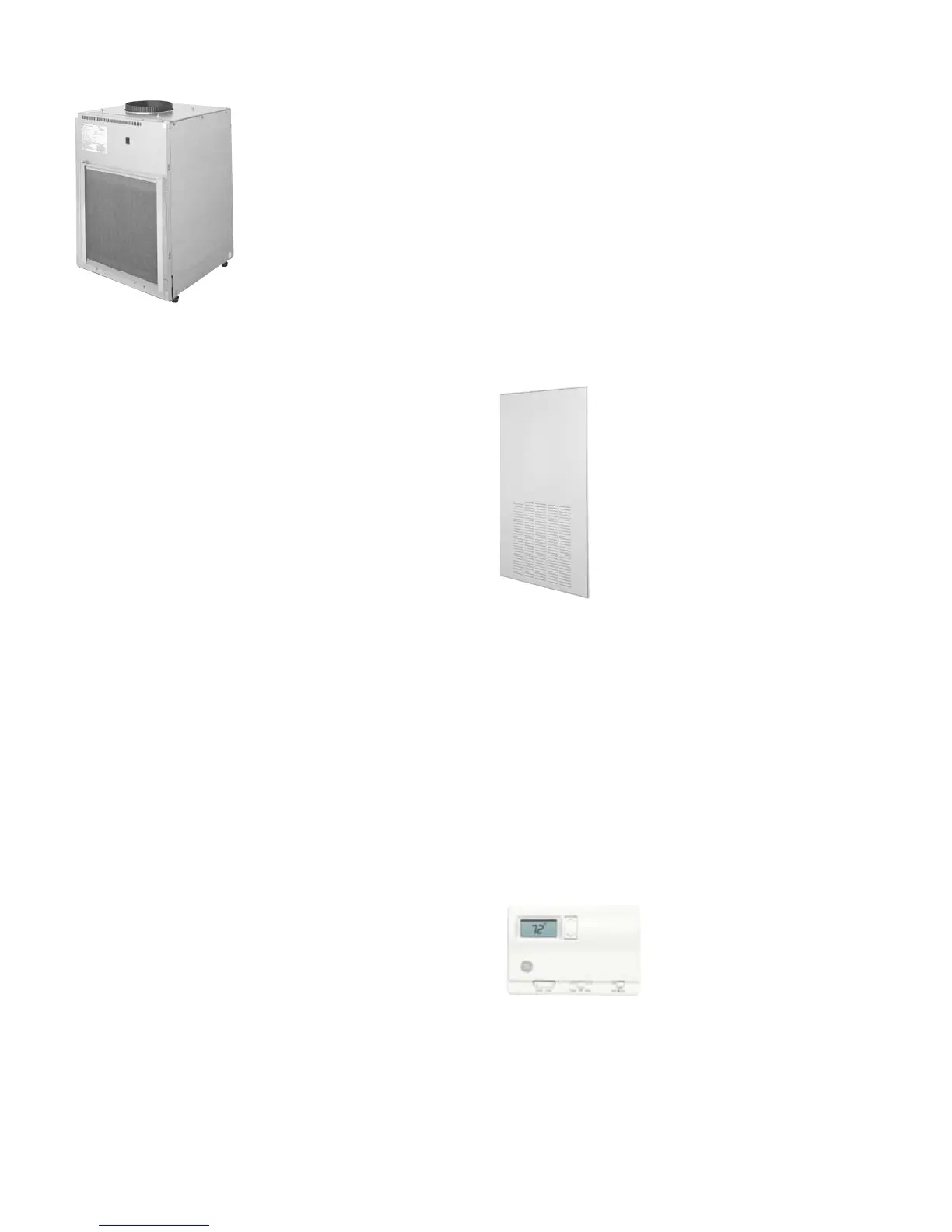
A wall-mounted access panel may be
used instead of the louvered door. In this
installation access to the unit is through a wall-mounted
access panel rather than a door. The return air is through the
panel. The access panel, model RAVRG1, requires a 28" wide by
48" high cutout in the wall and there is a filter bracket behind
the grille louvers.
The return air grille, model RAVRG2, may also be used and
is designed to be installed in a 20 3/8" by 20 3/8" cutout in a
flush closet door. In this installation, a filter can fit into the
bracket in the RAVRG2.
A field-supplied return air grille, with a minimum dimension of
20" by 20", may be used if mounted in a cutout in the door or
wall. When employing this method for return air, the filter is
installed in the bracket mounted on the unit.
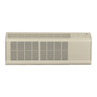
Remote Thermostat
The ZVAC units are controlled by a
wall-mounted thermostat. GE offers
a complete line of thermostats to
interface with the units or most 24-VAC
thermostats may be used. If a non-GE
thermostat is used, the compatibility of the thermostat with the
unit is the responsibility of the installer. The unit has an integral
transformer and no external voltage or transformer may be used.