Do you have a question about the GE Zoneline Generation-3 2800 Series and is the answer not in the manual?
Details the system for defrosting heat pumps to extend operation and savings.
Explains compressor protection during high outdoor temperatures by turning off the outdoor fan.
Describes using resistance heaters for faster room warming after mode changes.
Explains SmartFan for continuous cooling and cycling fan in heating for comfort.
Details automatic compressor shut-off to prevent indoor coil freezing during low temps.
Notes seven independent programmable limits for heating and cooling.
Explains interface for EMS to maintain fan operation during load shedding.
Highlights improved moisture removal capabilities, especially in Dry Air 25 models.
Explains the breakdown of the model number to identify unit specifications.
Describes the location and information found on the unit's model/serial tag.
Details how the serial number identifies the month and year of manufacture.
Outlines the procedure for checking and replacing the unit's run capacitor.
Provides instructions for checking compressor wiring and windings.
Lists cooling current in amps for different temperatures and BTUH units.
Shows evaporator air out temperatures for cooling mode in the 3800 series.
Provides guidance for determining the proper unit size for a given space.
Details line cord kits for connecting units to receptacles, including safety devices.
Explains permanent connection methods using sub-bases or junction boxes.
Covers NEC requirements for permanent connection of higher voltage units.
Details the 15A plug and its circuit schematic for 2.55/2.09 KW heaters.
Explains how jumpers and relays complete circuits for specific heater wattages.
Details the 20A plug and its circuit schematic for 3.45/2.82 KW heaters.
Explains circuit completion for 3.45 KW heat using jumpers and relays.
Details the 30A plug and its circuit schematic for 5.0/4.10 KW heaters.
Explains circuit completion for 5.0 KW heat using jumpers and relays.
Details the 15A, 265V plug and its circuit schematic for 2.55 KW heaters.
Explains circuit completion for 2.55 KW heat at 265V.
Details the 20A, 265V plug and its circuit schematic for 3.45 KW heaters.
Explains circuit completion for 3.45 KW heat at 265V.
Details the 30A, 265V plug and its circuit schematic for 5000W heaters.
Explains circuit completion for 5.0 KW heat at 265V.
Explains correct installation for optimal airflow and preventing hot air recirculation.
Details issues caused by poor airflow, leading to compressor overheating.
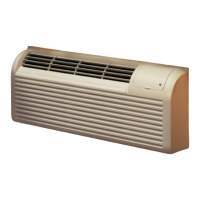
Describes the controls located behind the room cabinet door for unit operation.
Explains how units can be controlled by an externally mounted remote thermostat.
Covers systems allowing unit control from a central location like a reception desk.
Details wiring and compatibility considerations for remote thermostat installations.
Explains the function of various dip switch settings for unit configuration.
Explains the dip switch to activate the heat sentinel for preventing overheating.
Details the dip switch and thermistor dependency for freeze sentinel operation.
Troubleshooting steps for compressor issues, including resistance checks.
Guidance for diagnosing fan motor operation problems and resistance checks.
Instructions for checking thermistor values and their role in unit operation.
Procedures for checking heater circuits and protectors for continuity.
Further checks for dead units, including voltage and switch positions.
Troubleshooting steps for units controlled by a remote thermostat.
Illustrates the electrical connections for the 2800 series unit.
Provides a schematic view of the 2800 series unit's electrical layout.
| Brand | GE |
|---|---|
| Model | Zoneline Generation-3 2800 Series |
| Category | Air Conditioner |
| Language | English |