24
D
GB
F
E
96416-08.2020-DGbFEIRu
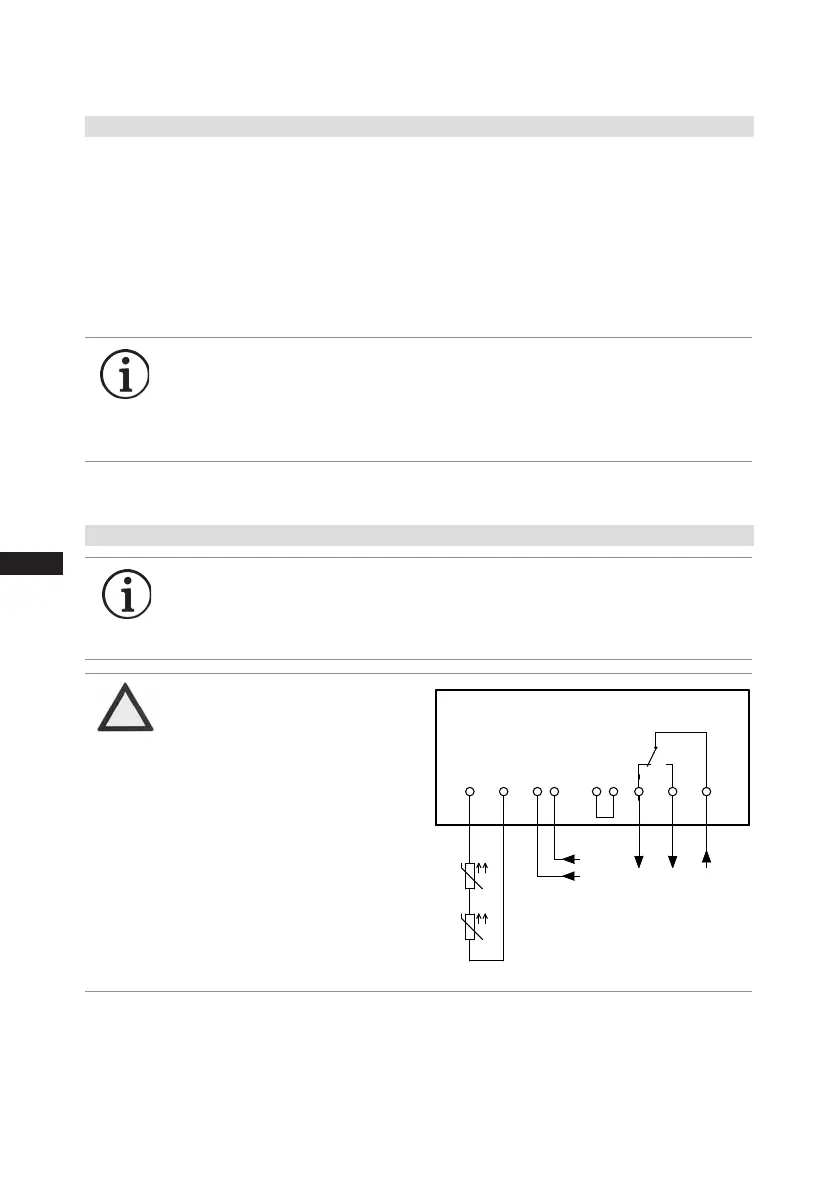
Terminalbox
Fig.13
ATTENTION
Measure circuit BT1 and BT2
(PTC sensor)mustnotcome
into contact with external
voltage.
Thiswoulddestroythetrigger
unitINT69GandPTCsensors.
7.6 ElectronictriggerunitINT69G
7.7 ConnectionofthetriggerunitINT69G
The compressormotor is tted withcold conductor temperature sensors (PTC)connected to the
electronic trigger unit INT69 Gin the terminal box.Incase of excess temperature in the motor
winding,theINT69Gdeactivatesthemotorcontactor.Oncecooled,itcanberestartedonlyifthe
electroniclockoftheoutputrelay(terminalsB1+B2)isreleasedbyinterruptingthesupplyvoltage.
The
hotgassideofthe compressorcanalsobeprotectedagainst overtemperatureusingthermal
protectionthermostats(accessory).
The
unittripswhenanoverloadorinadmissibleoperatingconditionsoccur.Findandremedy
the cause.
INFO Therelay switchingoutput is executed asa oatingchangeover
contact.Thiselectricalcircuitoperatesaccordingtothequiescent
currentprinciple,i.e.the relaydrops intoa theidle positionand
deactivatesthemotorcontactorevenincaseofasensorbreakor
open circuit.
INFO ConnectthetriggerunitINT69Ginaccordancewiththecircuitdia-
gram.Protectthetriggerunitwithadelayed-actionfuse(FC2)of
max.4A.Inordertoguaranteetheprotectionfunction,installthe
triggerunitastherstelementinthecontrolpowercircuit.
7 | Electrical connection
Οnderung
Klebeschilder
0
Datum Name
Datum
Bearb.
Gepr.
Norm
1
04.12.2009
Kelich
22.05.2015
Urspr.
2
Ers. f.
3
Ers. d.
4
Schaltplan
5 6 7
BOCK COMPRESSORS
8
=
+
9
Bl.
MP10 INt69 Bl.
MP10 INt69
INT69 G
Motor Protection MP10
Steuerstrom-
kreis
L
N
Steuerstrom-
kreis
L N
1112 14
B1 B2OG OG
+
-
BT1
Θ
X1 L1 L1 N N 43 43 11 12 14
L S M
X2 1 2 3 4 5 6
R1
R2
+
-
BT1
Θ
+
-
BT2
Θ
Controlcircuit
 Loading...