Grasso
Refri
eration Division
GRASSO SYSTEM CONTROL
Chap. 2 - 34 638660E_chapter2.doc 01.2004/1
Via this procedure of monitoring the ϕ value and adapting the capacity steps the intermediate pressure and
both discharge temperatures (T
int
and T
dis
) are kept within the valid operating conditions of the selected
compressor type.
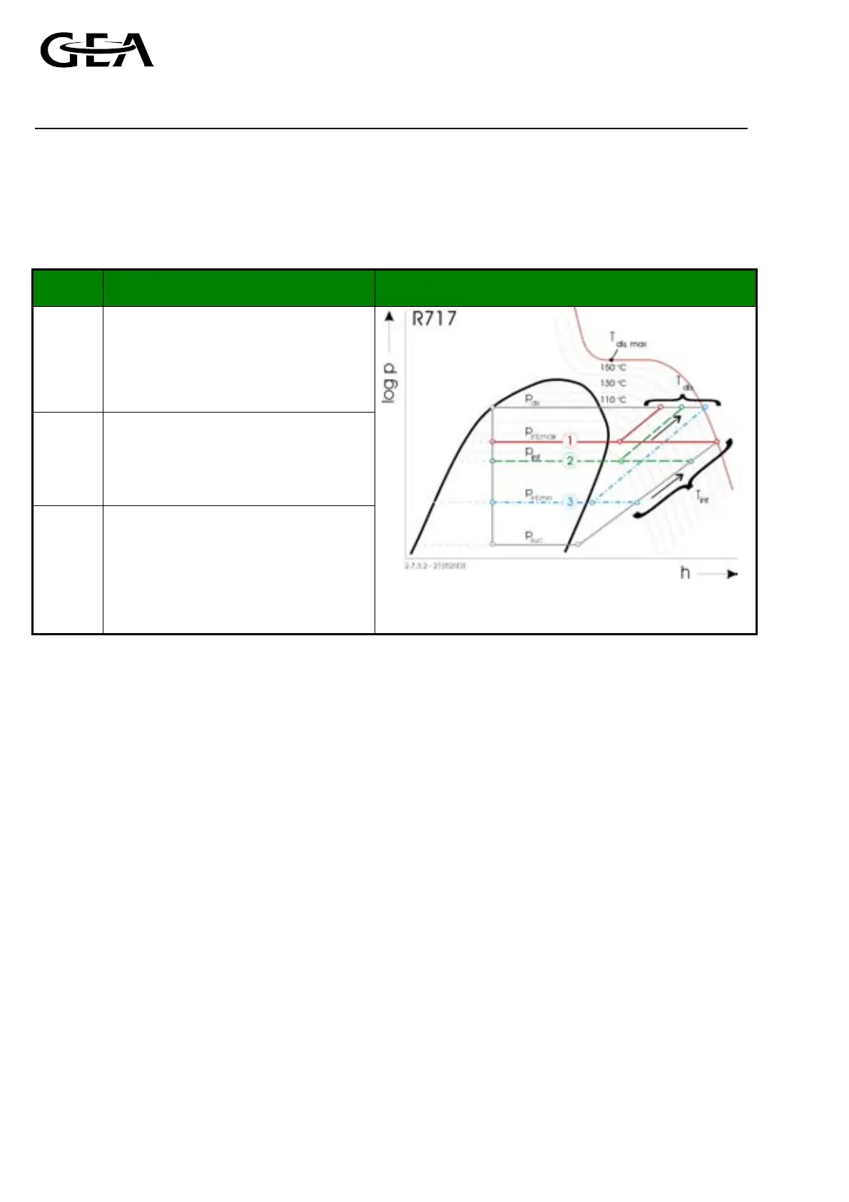
The relation between the intermediate pressure (p
int
), both discharge temperatures (intermediate temperature
at low pressure side T
int
and discharge temperature T
dis
), the suction pressure (p
suc
) and the discharge pressure
(p
dis
) are illustrated in the following diagram.
Example Explanation Diagram
1
max.
ϕ value
Maximum intermediate pressure
reached. As soon as a capacity step is
selected with wrong ratio of LP and HP
cylinders either ’Intermediate pressure
too high’ or ’Discharge temperature too
high’ alarm will be generated.
2
The intermediate pressure is between its
maximum and minimum limits. Both
discharge temperatures (T
int
and T
dis
) are
within the valid operating conditions.
3
min.
ϕ value
Minimum intermediate pressure
reached. As soon as a capacity step is
selected with wrong ratio of LP and HP
cylinders ’Intermediate temperature LP
too high’ alarm will be generated.
Figure 2.40, Log p — h diagram for Ammonia (R717) showing the
relation between intermediate pressure and both
discharge temperatures
) The GSC always intends to prevent wrong selection of the ratio of active LP and HP cylinders.
2.7.3.3 Pull down operation during start up and during normal operation of the compressor
If the suction pressure is high in the status display the message ’pull down’ will be shown. At the same time the
capacity is not increased. This additional status message can occur in combination with the status messages
’starting’ and ’running’ only.
This additional status messages is no indication of a failure, but it is an indication for the operator that further
increase of capacity is not possible (although capacity demand is present), because no valid capacity step with
higher capacity is available at the time.
To enable further capacity steps, the suction pressure must drop. Therefore this procedure is called ’pull down’.
If the capacity is increased without waiting for the suction pressure to drop, the compressor will stop with an
alarm ’intermediate pressure too high’. This procedure also uses the ϕ value to enable and disable capacity steps.
As soon as the suction pressure drops, further capacity steps are enabled. The pull down procedure is illustrated
in the following diagram.