Grasso
Refri
eration Division
GRASSO SYSTEM CONTROL
01.2004/1 638660E_chapter2.doc Chap. 2 - 35
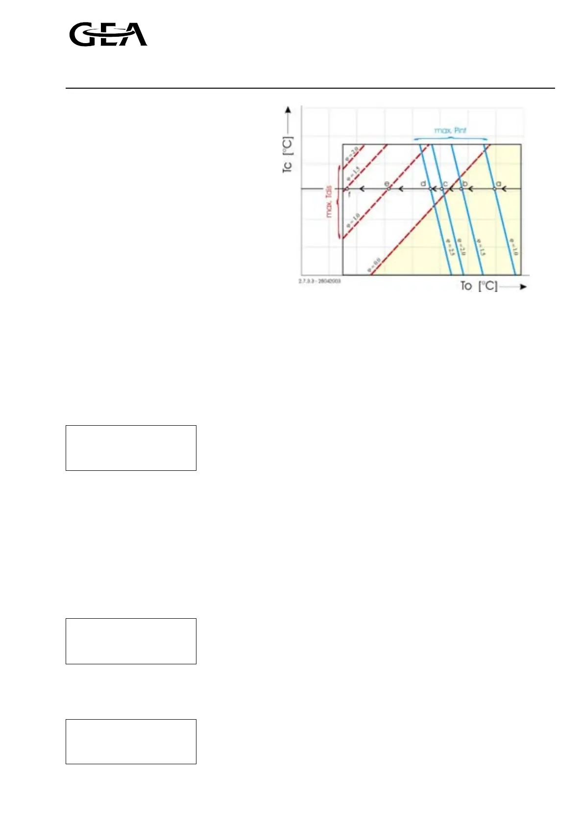
For a constant discharge pressure (T
c
) the
suction pressure (T
o
) moves along the line
’a — e’ from the right to the left. Not before
the suction pressure reaches point ’a’ (ϕ = 1.0)
the compressor is allowed to work as a two
stage compressor. Until this point the status
message ’Starting pull down’ is shown. After
this point the status message changes in
’Running pull down’ until the suction pressure
has dropped enough or no capacity demand is
present any longer.
The lines that form the intersections at points
’a’ through ’d’ change if the maximum
intermediate pressure limit (max p
int
) is
changed.
The dotted lines that form the intersections at
points ’e’ and ’f’ change if the maximum
discharge temperature limit (max T
dis
) is
changed.
Figure 2.41, Explanation of the pull down procedure
2.7.3.4 Fast pull down
The ’Fast pull down’ procedure (FPD) is similar with the normal ’Pull down’ procedure. Only that with the fast
pull down procedure an extra capacity solenoid is available (Sol. 5, FPD). The advantage of this extra solenoid is
that now an additional high pressure cylinder can be activated so that the suction pressure will drop faster and
so the running conditions are reached sooner.
This option can be activated in the configuration menu.
Fast Pull Down
Booster
Fast Pull Down: Selection between ’yes’ and ’no’ (two stage only)
<< Configuration 01 >>
) This option should be activated if the additional solenoid is installed only, otherwise the compressor
can be damaged.
2.7.3.5 Economiser control
The GSC is equipped with a self adapting controller for controlling the refrigerant injection for intermediate
cooling systems (economiser system) A and B. For a proper functioning of this controller the following settings
must be made in the configuration menu:
ECO system = A or B
Refrigerant injection = GSC
Injection valve (AKVA type) = type installed
ECO system
Injection control
ECO system: Selection between ’No ’, ’A ’, ’B ’, ’C ’, ’D ’ and ’2xB ’
Injection control: Selection between ’No ’ (mechanical injection) and
AKVA type
<< Configuration 01 >>
“GSC”(electronic injection)
AKVA type: Select installed AKVA type (’No, ’10-1’ through ’20-5’)
In the unit options menu the controller settings can be monitored and adjusted. For the controller is self
adapting the controller will overwrite changed parameter settings after a certain time.
Unit options
Economiser
Act val Parameter
Act val: Jump to ’Actual values’ menu for display of ECO values
Parameter: Jump to ‘Economiser’ menu for setting ECO parameters
<< I I >>