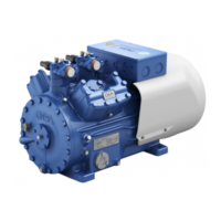
The GEA Compressor HG34P is a semi-hermetic four-cylinder reciprocating compressor designed for refrigeration systems. It features oil pump lubrication and a suction gas-cooled drive motor, ensuring efficient and reliable operation. The compressor is intended for use in refrigeration systems within the limits of application specified in the manual. Any other use, particularly in potentially explosive environments, is prohibited.
Function Description:
The HG34P compressor is designed to compress refrigerants in a closed refrigeration circuit. Its semi-hermetic design means the motor and compressor are integrated into a single sealed housing, reducing the risk of leaks and enhancing durability. The oil pump lubrication system ensures all moving parts are adequately lubricated, minimizing wear and extending the compressor's lifespan. The suction gas-cooled drive motor helps maintain optimal operating temperatures for the motor, contributing to its efficiency and longevity.
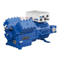
The compressor is equipped with cold conductor temperature sensors (PTC) connected to an electronic trigger unit (either MP10 or INT69 G) located in the terminal box. These sensors monitor the motor winding temperature. In case of excess temperature, the trigger unit deactivates the motor contactor, preventing damage. For the MP10 unit, readiness to operate is signaled by a green H3 LED, while excess motor winding temperature is indicated by a red H1 LED. For the INT69 G unit, the motor contactor is deactivated upon excess temperature, and can only be restarted after the electronic lock of the output relay is released by interrupting the supply voltage. An optional thermal protection thermostat can be installed to protect the hot gas side against overtemperature, with the H2 LED (red) indicating this protection function for the MP10 unit.
The compressor supports both direct start and star-delta start configurations, depending on the voltage supply. Star-delta start-up is only possible on a 230 V voltage supply. For direct start on 400 V Y, only direct start is permitted. To avoid current peaks during the starting phase, the use of a GEA ESS soft starting device (Electronic Soft Start) is recommended.
Important Technical Specifications:
The HG34P series includes several models, such as HG34P/215-4, HG34P/255-4, HG34P/315-4, and HG34P/380-4, with "S" variants indicating a more powerful motor for applications like air-conditioning.
- Displacement (50/60 Hz): Ranges from 18.8/22.6 m³/h to 33.1/39.7 m³/h.
- Voltage: 220-240 VΔ/380-420 VY (50 Hz) and 265-290 VΔ/440-480 VY (60 Hz).
- Maximum Operating Current (50 Hz): Ranges from 8.3 A to 18.7 A (Δ/Y).
- Maximum Power Consumption (50 Hz): Ranges from 5.0 kW to 11.1 kW. For 60 Hz operation, power consumption specifications should be multiplied by a factor of 1.2, while the maximum working current remains unchanged.
- Starting Current (rotor blocked): Ranges from 67/40 A to 134/77 A (Δ/Y).
- Weight: Ranges from 91 kg to 97 kg.
- Oil Charge: 1.3 Ltr.
- Sound Pressure Level: Ranges from 58 dB(A) to 67 dB(A), depending on the model and operating conditions (low temperature, normal cooling, air conditioning).
- Connections: Suction line (SV) connections are 22 mm (7/8 inch) or 28 mm (1 1/8 inch), and discharge line (DV) connections are 16 mm (5/8 inch) or 22 mm (7/8 inch) for solder connections.
- Refrigerants: Compatible with HFKW/HFC refrigerants (R134a, R404A/R507, R407C) and (H)FCKW/(H)CFC refrigerants (R22).
- Oil Type: Factory-filled with FUCHS Reniso Triton SE 55 for HFC refrigerants and FUCHS Reniso SP 46 for R22. Compressors with ester oil charge are marked with an "X" in the type designation.
- Operating Limits: Permissible ambient temperature range is -20°C to +60°C. Max. permissible discharge end temperature is 140°C. Max. permissible switching frequency is 8x/h. A minimum running time of 3 minutes in steady-state condition must be achieved.
- Maximum Permissible Overpressure (LP/HP): 19/28 bar.
Usage Features:
- Storage and Transport: Compressors should be stored at -30°C to +70°C with 10-95% relative humidity (no condensation). They must not be stored in corrosive, dusty, vaporous, or combustible environments. Transport should be done using the transport eyelet and lifting gear; manual lifting is not permitted.
- Setting Up: Requires an even surface or frame with sufficient load-bearing capacity. Single compressors should preferably be mounted on vibration dampers, while duplex and parallel circuits must be rigid. Adequate clearance for maintenance work and proper ventilation are essential. Attachments directly to the compressor are not allowed.
- Pipe Connections: Pipes and system components must be clean and free of scale, swarf, and layers of rust and phosphate. Air-tight pipes are crucial. Proper layout of suction and pressure lines is vital for smooth running and vibration behavior. Soldering should only be performed when the compressor is depressurized, with pipe supports removed from the valve, and the valve body cooled during and after soldering. Inert gas must be used during soldering to inhibit oxidation.
- Shut-off Valves: Before opening or closing, the valve spindle seal must be released by approximately 1¼ turns counter-clockwise. After activation, the seal should be re-tightened clockwise.
- Refrigerant Charge: Liquid refrigerant should be added directly to the condenser or receiver with the compressor switched off, breaking the vacuum. If topping up after starting, it can be added in vapor form on the suction side or, with precautions, in liquid form at the evaporator inlet. Overfilling must be avoided. Zeotropic blends (e.g., R407C) must always be added in liquid form to prevent shifts in concentration. Liquid refrigerant should not be poured through the suction line shut-off valve on the compressor, and mixing additives with oil and refrigerant is not permitted.
- Start-up: Ensure both shut-off valves are open before starting. Verify proper functioning of safety and protection devices. After switching on, let the compressor run for at least 10 minutes and check the oil level in the sight glass.
- Avoid Slugging: Proper refrigeration plant design, compatibly rated components, and suction gas superheating of at least 7-10 K at the compressor input are crucial. Measures like liquid traps and solenoid valves in the liquid line are recommended for critical systems. No refrigerant movement should occur in the compressor while it is at a standstill.
Maintenance Features:
- Preparation: Before any maintenance, switch off the compressor, secure it against restart, relieve system pressure, and prevent air infiltration. After maintenance, reconnect the safety switch, evacuate the compressor, and release the switch-on lock.
- Oil Change: Not mandatory for factory-produced series systems. For field installations or when operating near application limits, the first oil change should be performed after 100-200 operating hours, then approximately every 3 years or 10,000-12,000 operating hours. Used oil must be disposed of according to national regulations.
- Annual Checks: Regular checks include oil level, leak tightness, running noises, pressures, temperatures, and the function of auxiliary devices such as the oil sump heater and pressure switch.
- Spare Parts: Genuine GEA spare parts are recommended. Spare parts kits available include:
- Set of gaskets (Ref. No. 08534)
- Valve plate kit (Ref. No. 80305 for 215-4/255-4, 80306 for 315-4/380-4)
- Oil pump kit (Ref. No. 08324)
- Decommissioning: Close the shut-off valves, drain the refrigerant (dispose of according to regulations), depressurize the compressor, undo fastening screws of shut-off valves, and remove the compressor using appropriate hoist. Dispose of oil according to national regulations.