Do you have a question about the GEA T.VIS A-15 and is the answer not in the manual?
Details on the document's content, binding character, and illustrations.
Defines proper usage and lists improper operating conditions.
Outlines the operator's responsibilities for safe handling and operation.
Covers general safety principles and potential dangers.
Lists additional applicable regulations and safety rules.
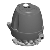
Explains the core function and operation mechanism of the control top.
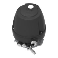
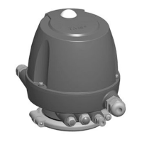
Describes control tops with and without solenoid valves.
Explains the operational logic and timing of the control top buttons.
Guidelines for proper storage and transport to prevent damage.
Explains the components of the type plate for product identification.
Technical specifications for the IO-Link communication interface.
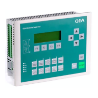
Lists related equipment with part numbers.
Safety principles to follow during assembly and installation.
Step-by-step guide for correctly connecting pneumatic hoses.
Explains port usage for lifting functions with two solenoid valves.
Details connections for double-disk lift or external stroke with two valves.
Explains port usage for spreader lift with two solenoid valves.
Details connections for valve and double-disk lifting with three valves.
Explains port usage for double-disk lift with three pilot valves.
Details connections for multiple lift functions using four pilot valves.
Provides a visual overview of electrical connection points.
Wiring details for the 8-pin M12 connector.
Wiring details for the 12-pin M12 connector.
Wiring details for AS-Interface using a 5-pin M12 connector.
Wiring details for DeviceNet using a 5-pin M12 connector.
How to swap indicator colors and its effect on feedback signals.
Specific instructions for mounting on VARIVENT valve types.
Steps for fitting the control top onto FLOWVENT valves.
Detailed installation for specific VARIVENT mixproof valve types.
Instructions for mounting on T-smart 8000 butterfly valves.
Guides for mounting on ECOVENT N_ECO and W_ECO valves.
Mounting guide for VESTA H_A valves.
Mounting guide for T-smart single-seat and double-seal valves.
Cautionary notes and procedure for replacing control tops.
Safety principles for initial commissioning and general operation.
Steps to activate and commission the control top without solenoid valves.
Steps to assemble the initiator holder for double-disk valves.
Steps to install the proximity switch correctly.
How to verify the proper function of the adjusted proximity switch.
Steps to assemble the proximity switch holder for MT-DA valves.
Steps to assemble the proximity switch holder for PMO valves.
Steps to adjust the proximity switch gap.
How to verify the proximity switch function.
States the objectives for test procedures 1 and 2.
Describes the manual process for verifying seat lifting detection.
Details components relevant to test procedures.
Step-by-step guide for performing Test Procedure 1.
Explains Test Procedure 2 for verifying system interlocks.
Safety principles to ensure safe operation of the component.
Information on factory settings and adjustments available in programming mode.
Configuration options for the LEFF function on specific valve types.
Guidelines for cleaning the control top safely and effectively.
Safety rules and procedures before performing maintenance or repair.
Safety guidelines for dismantling the control top.
Lists the different possible configurations of the control top.
Steps for safely removing the control top's cap.
Guidance for installing the printed circuit board.
Steps for removing the sensor module.
Instructions for fitting the logic element NOT.
Procedure for replacing seals on the actuator base.
Maintenance tasks for air path components.
Troubleshooting guide for common malfunctions and their solutions.
Safety procedures for safely shutting down the component.
Instructions for environmentally responsible disposal of the component.
Glossary of abbreviations and technical terms used in the manual.
| Input Voltage | 24 V DC |
|---|---|
| Protection Class | IP67 |
| Ingress Protection | IP67 |
| Communication Protocols | AS-Interface, DeviceNet |
| Housing Material | Stainless Steel |
| Touch Technology | Capacitive |
| Mounting | Valve Mounting |