Do you have a question about the GEA T.VIS M-15 and is the answer not in the manual?
Details about the document's binding character, illustrations, and symbols used.
Specifies the importance of following manufacturer's instructions for safe operation.
Explains that illustrations are simplified and may differ from the actual product.
Illustrates how important information is highlighted using symbols and formatting.
Provides the official address of the manufacturer, GEA Tuchenhagen GmbH.
Lists contact information including phone, fax, and email for inquiries.
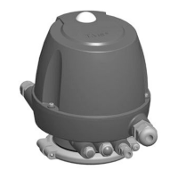
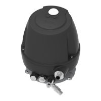
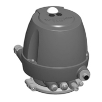
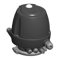
Defines the proper application of the T.VIS M-15 control top and its available configurations.
Outlines prerequisites for reliable and safe component operation, including proper handling.
Details conditions under which operational safety cannot be guaranteed.
Assigns responsibility to the operating company for safe component handling and monitoring.
Explains IP ratings (IP66, IP67, IP69k) concerning protection against solids and humidity.
Provides fundamental safety advice for operating the component safely.
Lists key principles for ensuring safe operation of the valve and component.
Specifies safety principles for working with electrical equipment and modifications.
Describes the necessary training and qualifications for personnel working on the component.
Details the use and importance of warning, prohibition, and mandatory signs.
Explains the meaning of warning and prohibition signs on the control top.
Identifies residual dangers and necessary safety measures for life and property.
Provides precautions for handling components sensitive to electrostatic discharge (ESD).
Notes on ensuring safety when working in or around danger zones on the component.
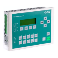
Provides a detailed overview of the control top's components and assembly.
Explains the overall functionality and operation of the T.VIS M-15 control top.
Describes how the control top functions using a microprocessor and pneumatic/electronic modules.
Details the function of the control top when used solely as a position indicator.
Explains the function of the control top when equipped with solenoid valves for actuation.
Explains the purpose and format of the control top's type plate for identification.
Provides detailed electrical specifications for the 24V DC interface module.
Details the technical specifications for the AS-Interface adapter module.
Provides technical specifications for the DeviceNet adapter module.
Lists technical data and material numbers for various control top components.
General safety precautions to be observed during installation and assembly.
Instructions for correctly cutting and connecting pneumatic hoses.
Details pneumatic connection configurations for different solenoid valve setups.
Describes pneumatic connections for control tops with one or no solenoid valves.
Details pneumatic connections for control tops equipped with two solenoid valves.
Explains pneumatic connections for control tops with three solenoid valves.
Provides instructions for making electrical connections to the control top.
Shows an exploded view of the control top with numbered parts for reference.
Details the steps for connecting the ASI (AS-Interface) cable.
Guides on wiring the control top for 24 V DC operation.
Wiring details for the 5-pin M12 connector, including pin assignments.
Describes the function of terminals on the interface module with two sensors.
Presents a wiring diagram for 24V DC control systems using P-logic.
Provides the wiring diagram specifically for the T.VIS M-15 in 24 V DC configuration.
Explains the visual indicators and status visualization on the control top.
Details the status indications provided by the illuminated dome.
Describes how to install and remove the control top on various valve types.
Instructions for mounting the control top onto VARIVENT and STERICOM valve types.
Provides a warning and procedure for replacing control tops, emphasizing switch bar compatibility.
Crucial safety precautions for initial commissioning and operation.
Principles for correctly commissioning the control top and ensuring connections.
Detailed steps for adjusting sensors S1 and S2 for accurate valve position detection.
Procedure for adjusting the start position of the valve disk with sensor S1 in the 'up' position.
Specific instructions for adjusting sensors on T-smart butterfly valves.
Describes test procedures to verify valve function and interlocks.
Procedure to verify and ensure detection devices for upper and lower valve seats are functional.
Confirms correct operation of system interlocks during CIP switching.
General safety guidelines for monitoring and operating the component.
Safety rules for performing maintenance and repair work on electrical equipment.
Checks to ensure all parts, connections, and screws are securely fastened.
Step-by-step guide for disassembling the control top into its constituent parts.
Instructions on how to safely remove the cap from the control top.
Procedure for disconnecting and removing solenoid valves and control plates.
Instructions for safely removing the pneumatic block from the control top.
Lists common malfunctions, their signaling, causes, and recommended remedies.
Safety principles to follow when shutting down the component.
Guidelines for environmentally safe disposal of the component and its materials.
Contains lists of terms, abbreviations, and other supplementary information.
Provides definitions and explanations for abbreviations and technical terms used.
| Brand | GEA |
|---|---|
| Model | T.VIS M-15 |
| Category | Control Systems |
| Language | English |