9
System connection
The communication cable provided with the heat pump must be connected to the RS485 communication port of the
spa control.
The power cable connects to the spa control using 6,35mm (0,250'') quick connect female terminals. Ensure that all
female terminals are correctly and completely seated on the printed circuit terminals for proper current ratings.
The connection must be done according to the following tables:
External breaker
The in.temp is intended to be powered by the spa control using the included power cable but it can also be powered by
an external circuit breaker.
If an external circuit breaker is used to power the in.temp, make sure the cord used comply with all local regulation.
To avoid unnecessary shedding of accessories when the in.temp or a different heat pump is not powered by the spa
control, set the heat pump current to zero (0) through your spa user interface.
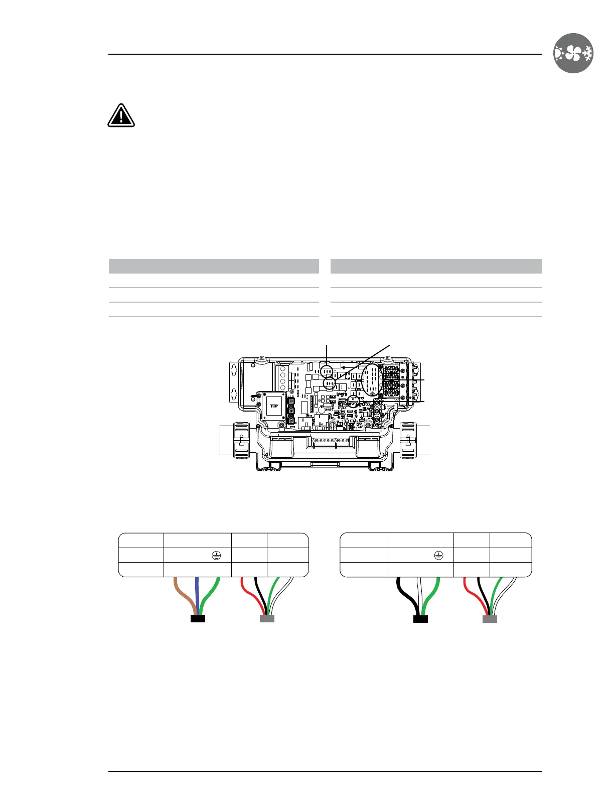
Terminal box
The terminal box is located behind the terminal cover and allows access to the communication and power connections.
Connections
Turn off power before connecting the in.temp to the spa control system.
CE Model
Brown Main line P28, P30 or P32 tab (F2)
Blue Any Neutral (N) tab
Green/Yellow Any Ground (G) tab
NA* Model
Black Main line P31, P33 or P36 tab (F3)
White Any Line 2 (L2) tab
Green Any Ground (G) tab
P28-P30-P32 P31-P33-P36
in.ye control system
Neutral (N), L2 and Ground (G) tabs
Communication cable Communication cable
RS485 port (P83)
Power cable (CE) Power cable (NA*)
Terminal ID
Brown Red Black Green WhiteBlue
Green/
Yellow
Wire color
Signal 220 V~240 V, 50 Hz 12V RS-485
L + - B AN
Terminal ID
Black Red Black GreenGreen WhiteWhite
Wire color
Signal 240 V ± 5%, 60 Hz 12V RS-485
L + - B AN
*North American
 Loading...