Do you have a question about the Gefen EXT-RMT-MATRIX-444 and is the answer not in the manual?
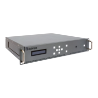
Describes buttons used to switch inputs on the matrix.
Details LEDs indicating the currently selected source.
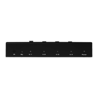
Describes the CAT-5e connection for control.
Describes the serial port for RS-232 remote control.
Mentions the DIP switch bank for configuration.
Describes the serial port for connecting to a Gefen product.
Describes the power receptacle for the DC power supply.
Details the RJ-45 jacks for CAT-5e connections to the Matrix RMT.
Instructions for connecting the CAT-5e/6a cable to the matrix.
Explains switching via buttons or optional IR remote.
Visual representation of the connection setup for the 4x4 Matrix RMT.
Details the DIP switches on the bottom of the unit.
Explains the function of DIP switch 4 for RS-232 feedback control.
Instructions for connecting CAT-5/6 cables to the CAT5 to Serial unit.
Specifies connecting a non-null modem serial cable.
Visual representation of the connection setup for the CAT5 to Serial unit.
Details the pin usage for the RS-232 serial interface.
Specifies serial communication parameters like baud rate and data bits.
| Input Ports | 4 |
|---|---|
| Output Ports | 4 |
| HDMI Version | 2.0 |
| Power Supply | 5V DC |
| Maximum Pixel Clock | 600 MHz |
| Maximum TMDS Throughput | 18 Gbps |
| Video Input Connectors | HDMI |
| Video Output Connectors | HDMI |
| RS-232 Port | Yes |
| IP Control Port | Yes |
| IR Ext Port | Yes |
| USB Port | No |
| Video Bandwidth | 18 Gbps |
| Supported Resolutions | Up to 4K@60Hz |
| Control | RS-232, IR, IP |
| Operating Temperature | 0°C to 40°C |
| Net Weight | 4.4 lbs |