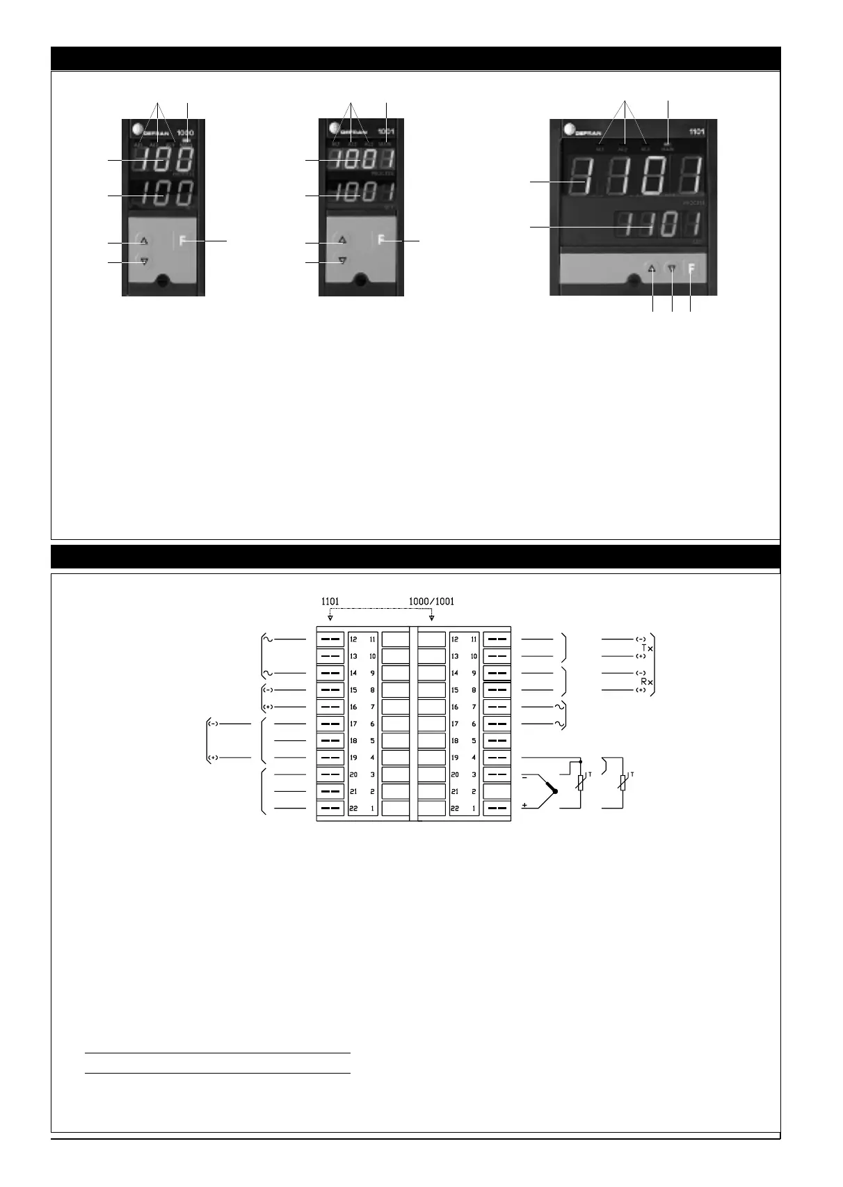
3 • DESCRIPTION OF FACEPLATE
11
4 • CONNECTIONS
A - Digit height: 14mm (1000), 10mm (1001), 20mm (1101), green.
Value of variable controlled to 3 digits (1000) 3, 5 digits (1001 – 1101) with decimal
point on appropriate scales.
Positive (HI) or negative (LO) off-scale message. Message for broken/incorrect con-
nection of probe (SBR: open circuit / ERR: probe reversed) and display of configura-
tion and calibration messages.
B - Digit height: 14mm (1000), 10mm (1101), 14mm (1101), green.
Setpoint value.
Alarm limit range –199...+999 (1000) –999+1999 (1001 – 1101).
Alarm limits are accompanied by flashing of AL1, AL2, AL3/HB LEDs. Main output
value in percentage (0...99%) followed by letter P.
Parameter values and configuration data.
C - Function key
Accesses setpoint and alarm functions (each function is specified by flashing of LED
for reading and/or changing of values).
If the F key is not pressed to confirm a change, saving is done automatically after 10
sec. and the display returns to setpoint value.
The F key accesses the various configuration and saving procedures for changed
settings.
D - Raise Key / E - Lower Key
These keys raise or lower the value of the displayed function.
The raising (lowering) speed is proportional to the time the key is pushed. The pro-
cedure is not cyclical. When the maximum (minimum) of the setting range is reached
with the key pushed, the raise (lower) function stops.
F - Main output on. Green LED.
G - Alarm signal. Red LED.
Front panel protection IP54 (IP65 available)
B
E
GF
D
A
C
B
E
GF
D
A
C
GF
B
ED
A
C
SERIAL
LINE
POWER SUPPLY
TC
PT100
3 wires
PTC Pt100
2 wires
Current input from CT 5Aac
MAIN
(D2)
MAIN
CONTINUOUS
CONTROL
OUTPUT
AL2
AL3/HB
AL1
21 connections are available for 6.35 mm faston terminals.
Main inputs
Inputs from TC or RTD (2 wires) are attached to faston 1 (positive) and 3 (negative).
(Short circuit 3 and 4 for RTD with 2 wires).
For RTD with 3 wires, the single wire is attached to faston 1; for the remaining wires, one goes
to faston 3 and the other to 4.
Input from current transformer (HB function)
If the instrument accepts this input, it is attached to fastons 6 and 7. Secondary current input
for CT, impedance 20mW, 5A, 50/60 Hz.
Power supply
Voltage (100...240Vac) is attached to fastons or terminals 12 and 14. A version with
11...27Vac/dc voltages is available.
Fuse
Inside instrument, not replaceable by user.
Power supply Type Current Voltage
100...240Vac T 0,5A 250V
11...27V T 1,25A 250V
Main output
Relay output to terminals or fastons 19 (N.O.) 18 (C) and 17 (N.C.); contact capacity
5A/250Vac at cosj = 1.
Logic output type D2 24V/20mA max. is available to fastons 16 (positive) and 15 (negative).
Continuous output to terminals or fastons 19 (+) and 17 (-) as alternate to relay output.
Alarm outputs
For alarm relays:
terminals or fastons 20 (N.C.) 21 (C) and 22 (N.O.) for alarm 1; terminal faston 11 and 100
(N.C. or N.O.) for alarm 2; terminals 9 and 8 (N.C. and N.O.) for alarm 3/HB.
NC contacts are available for alarms 2 and 3 by changing the jumpers. Contact capacity is 5A
for alarm 1 and 3A/250Vac for alarms 2 and 3.
Digital communication (Current loop / 485)
If the instrument accepts a 1200 baud Passive Current Loop interface, the reception diode is
available at fastons 8 (Rx+) and 9 (rx-); transmission transistor to fastons 10 (Tx+) and 11 (tx-).
In standard configuration for parallel connection on the serial line, the resistance in series to
the diode is 1K Ohm; 100 Ohm to the transistor collector.
For the series connection, the resistance in series to the diode is 100 Ohm. If the instrument
accepts 1200...9600 baud 4-wire RS485 interface, reception is available to fastons 8 (Rx+)
and 9 (Rx-); transmission to fastons 10 (Tx+) and 11 (Tx-) (see hardware configuration).

 Loading...


